T-- - - - - -, SHIELD
I
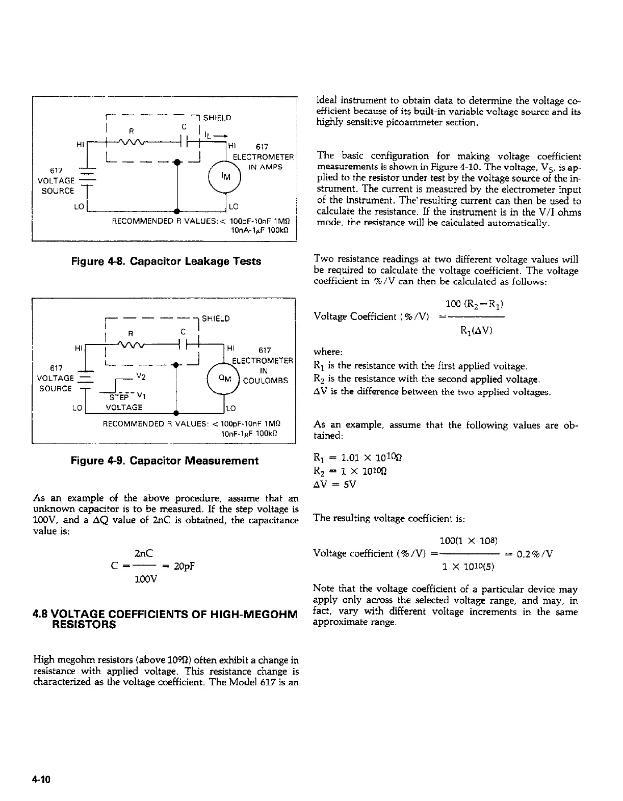
RECOMMENDED R VALUES:< IOOpF-10nF 1MR
IOnA-l+F 1OOkR
Figure 4-8. Capacitor Leakage Tests
RECOMMENDED R VALUES: < lOO,+lOnF IMR
,OnF.l,J 1OOkll
Figure 4-9. Capacitor Measurement
As an example of the above procedure, assume that an
unknown capacitor is to be measured. If the step voltage is
1LXW. and a AQ value of 2°C is obtained, the capacitance
value is:
2°C
Cc---
= 20pF
1OQv
4.8 VOLTAGE COEFFICIENTS OF HIGH-MEGOHM
RESISTORS
ideal instrument to obtain data to determine the voltage co-
efficient because of its built-in variable voltage source and its
highly sensitive picoammeter section.
The basic configuration for making voltage coefficient
measurements is shown in Figure 4-10. The voltage, Vs, is ap-
plied to the resistor under test by the voltage source of the in-
strument. The current is measured by the electrometer input
of the instrument. The! resulting current can then be used to
calculate the resistance. If the instrument is in the V/I ohms
mode, the resistance will be calculated automatically.
Two resistance readings at two different voltage values will
be required to calculate the voltage coefficient. The voltage
coefficient in %/V can then be calculated as follows:
100 CR,--R,)
Voltage Coefficient (%/V) =
R,(AV)
where:
R, is the resistance with the first applied voltage.
R, is the resistance with the second applied voltage.
AV is the difference between the two applied voltages.
As an example, assume that the following values are ob-
tained:
R, = 1.01 x IOW
RZ = 1 x loWI
AV = 5V
The resulting voltage coefficient is:
X0(1 X 10⁸)
Voltage coefficient (%/VI =
= 0.2%/V
1 x lolo
Note that the voltage coefficient of a particular device may
apply only across the selected voltage range, and may, in
fact, vary with different voltage increments in the same
approximate range.
High megohm resistors (above 10%) often exhibit a change in
resistance with applied voltage. This resistance change is
characterized as the voltage coefficient. The Model 617 is an
4-10