EasyManua.ls Logo

Keithley 617 User Manual

Keithley 617
183 pages
To Next Page IconTo Next Page
To Previous Page IconTo Previous Page
Page #88 background imageLoading...
Page #88 background image
PROGRAM COMMENTS
10 REMOTE 727
20 DIM AS 1251
Send remote enable.
30 OuTPIJT 727:“UOX” Send UO command.
40 DW”mdlFRRCZNTOBGD Display UO word values
QMMKYY”
50 ENTER 727;A$
Obtain UO status from in-
strument.
Display UO status word
Send U1 command.
Get error condition
word.
Display error condition
word.
Send U2 command.
Get data condition word.
Display data condition
word.
Get normal reading.
Display normal reading.
60 DISP A$
70 OUTPUT 727;“Ulx”
80 ENTER 727;A$
90 DISP A$
100 OUTPUT 727:“U2X”
110 ENTER 727;A!J
120 DISP A$
130 EmR 727:A$
140 DISP A$
150 END
80 PRINT RD$
90 CMD$=“UlX”:CALL IBWRT
(M617%,CMD5)
100 RD$=SPACE$(ZS):CALL IBRD
(M617%,RD$)
1.10 PRINT RD$
120 CMD$=“UZX”:CALL IBWRT
(M617%,CMD$)
130 RD$=SPACE$(2S):CALL IBRD
(M617%,RD$)
140 PRIh’T RD$
150 RD$= SPACE$(25):CALL IBRD
(M617%,RD$)
160 PRINT RD$
170 V% =O:CALL IBONL
(BRDO%,V%)
180 CALL IBONL (M617%,V%)
Display status word.
Send Ul command.
Get error condition
word.
Display error condi-
tion word.
Send IJ2 command.
Get data condition
word.
Display data condi-
tion word.
Get normal reading.
Display normal
reading.
Close the board file.
Close the instrument
file.
Press the conmuter F2 function kev to run the moeram. The
.
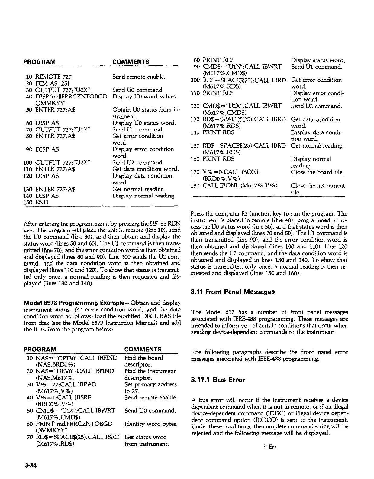
After entering the program, run it by pressing the HP-85 RUN
instrument is placed in remote (line 40). programmed to ac-
key. The program will place the unit in remote (line 10). send
cess the UO status word (line 50). and that status word is then
the UO command (line 30). and then obtain and display the
obtained and displayed (lines 70 and 80). The Ul command is
status word (lines 50 and 60). Th e Ul command is
then trans-
then transmitted (line 90). and the error condition word is
mitted (line 70). z
md the error condition word is thj en obtained
then obtained and displayed (lines 100 and 110). Line 120
and displayed (lines 80 and 90). Line 100 sends the U2 com-
then sends the U2 command, and the data condition word is
mand, and the data condition word is then obtained and
obtained and displayed in lines 130 and 140. To show that
displayed (lines 110 and 120). To show that status is transmit-
status is transmitted only once, a normal reading is then re-
ted only once, a normal reading is then requested and dis-
quested and displayed (lines 150 and 160).
played (lines 130 and 140).
3.11 Front Panel Messages
Model 8573 Programming Example-Obtain and display
instrument status, the error condition word, and the data
condition word as follows: load the modified D--’ - IS file ‘tCL.LI~
The Model 617 has a number of front panel messages
from disk (see the Model 8573 Instruction Manual) and add
associated with IEEE-488 programming. These messages are
the lines from the program below:
intended to inform you of certain conditions that occur when
sending device-dependent commands to the instrument.
PROGRAM
COMMENTS
10 NA!J= “GPIBO” :CALL IBFIND Find the board
(NA$,BRDO%) descriptor.
20 NA$=“DEVO”:CALL IBFIND Find the instrument
(NA!f+M617%)
30 V% =27:CALL IBI’AD
(M617%,V%)
40 V%=l:CALL IBSRE
descriptor.
Set primary address
to 27.
Send remote enable.
(BRDO%,V%)
50 CMD$=“LIOX”:CALL IBWRT Send UO command.
(M617%,CMD$)
60 PRINT”mdlFRRCZNTOBGD Identifv word bvtes.
QMMKYY”
70 RD$=SPACE$QS):CALL IBRD Get status word
(M617%,RD$) from instrument.
The following paragraphs describe the front panel error
messages associated with IEEE-488 programming.
3.11.1 Bus Error
A bus error will occur if the instrument receives a device
dependent command when it is not in remote, or if an illegal
device-dependent command (IDDC) or illegal device depen-
dent command option (IDDCO) is sent to the instrument.
Under these conditions, the complete command string will be
rejected and the following message will be displayed:
b Err
3-34

Table of Contents

Other manuals for Keithley 617

Question and Answer IconNeed help?

Do you have a question about the Keithley 617 and is the answer not in the manual?

Keithley 617 Specifications

General IconGeneral
BrandKeithley
Model617
CategoryMeasuring Instruments
LanguageEnglish

Summary

Warranty Information

Warranty

Details the warranty terms and conditions for the product and specific components.

Specifications

Specifications

Details the electrical and performance specifications for the Model 617 electrometer.

Safety Precautions

Safety Precautions

Advises on essential safety measures to avoid injury and instrument damage during operation.

Section 1: General Information (Continued)

Unpacking and Getting Started

Details unpacking, inspection, and initial steps to operate the Model 617.

Section 2: Operation

2.2 Power Up Procedure

Details the steps for connecting power and turning on the instrument.

2.3 Power Up Self Test and Display Messages

Explains the self-test routine and potential display messages upon startup.

Section 2: Operation (Continued)

2.4 Front Panel Familiarization

Provides an overview of the Model 617's front panel layout, controls, and indicators.

2.7 Basic Measurement Techniques

Introduces fundamental procedures for making voltage, resistance, charge, and current measurements.

2.7.2 Input Connections

Details how to connect input signals to the rear panel INPUT connector.

2.7.4 Guarded Operation

Explains the concept and application of guarding to minimize leakage and improve measurements.

2.7.5 Making Current Measurements

Details the procedure for measuring low-level currents, including picoampere ranges.

2.7.6 Making Charge Measurements

Describes how to measure charge using the Model 617's coulombs ranges.

2.7.7 Resistance Measurements

Explains how to measure resistance using constant current and voltage methods.

2.8 Using The Voltage Source

Explains how to use the Model 617's built-in voltage source for V/I measurements.

2.10 Using External Feedback

Explains how to extend capabilities using external feedback networks.

2.11 Using Zero Correct and Baseline Suppression

Covers instrument offset cancellation and baseline value storage.

2.11.2 Using Suppression

Details how to store an offset value and subtract it from subsequent readings.

2.13 External Triggering

Explains how to trigger the instrument using external BNC connectors.

2.4.1 Controls

Describes the function and operation of each front panel control button.

2.5.3 Calibration

Introduces the digital calibration program for front panel or IEEE-488 bus use.

2.7.3 Making Voltage Measurements

Provides step-by-step instructions for measuring DC voltages with the Model 617.

2.8.1 Basic Operating Procedure

Guides on connecting and adjusting the voltage source output.

2.11.1 Zero Correct and Zero Check

Explains how to use Zero Correct and Zero Check to cancel internal offsets.

2.12 Data Storage

Describes the internal 100-point data store mode for logging readings.

2.13.1 External Trigger

Details continuous and one-shot triggering modes via the external trigger input.

2.14 Measurement Considerations

Discusses factors affecting measurements at low signal levels.

2.8.2 V/I Resistance Measurements

Describes how to measure high resistances using the voltage source and electrometer.

Section 3: IEEE-488 Programming

Section 3: IEEE-488 Programming (Continued)

3.4 Bus Commands

Covers device commands, grouped into uniline, multiline, and device-dependent categories.

3.7.2 Bus Connections

Details how to connect the Model 617 to the IEEE-488 bus using appropriate cables.

3.7.3 Primary Address Programming

Explains how to check and set the instrument's primary address for bus communication.

3.8 Software Considerations

Discusses software aspects for IEEE-488 controllers like HP-85 and IBM-PC.

3.9 General Bus Command Programming

Covers general bus commands like DCL, REN, IFC, LLO, GTL, SDC, GET, SPE, SPD.

3.10 Device-Dependent Command Programming

Details commands controlling modes like function, range, trigger, and data format.

3.10.2 Function (F)

Describes commands to select measurement functions like Volts, Amps, Ohms, Coulombs.

3.10.3 Range (R)

Explains commands for controlling instrument sensitivity and selecting measurement ranges.

3.10.4 Zero Correct and Zero Check (Z and C)

Details commands for canceling internal offsets and zeroing the instrument.

3.10.5 Baseline Suppression (N)

Explains commands to store an offset and subtract it from subsequent readings.

3.10.9 Voltage Source Value (V)

Details commands for programming the built-in voltage source output.

3.4.5 Device-Dependent Commands

Describes commands specific to device configuration, controlling functions like mode and range.

3.10.8 Data Store Mode

Explains how to use the data store for logging readings and setting intervals.

3.10.11 Calibration Value (A)

Describes commands for setting calibration values for ranges and functions.

Section 4: Applications

4.2 Insulation Resistance Measurements

Details how to measure high insulation resistances using constant current and voltage methods.

Section 4: Applications (Continued)

4.3 High Impedance Voltmeter

Explains using the Model 617 as a high-impedance voltmeter with minimal circuit loading.

4.4 Low-Level Leakage Current Measurements

Guides on measuring low-level currents like nanoamperes and picoamperes.

Section 5: Performance Verification

Section 5: Performance Verification (Continued)

5.5 Verification Procedures

Provides detailed procedures for verifying accuracy of volts, ohms, amps, and coulombs functions.

Section 7: Maintenance

Section 7: Maintenance (Continued)

7.4.5 Front Panel Calibration

Provides step-by-step instructions for calibrating from the front panel.

7.4.11 Amps Calibration

Provides calibration steps for the amps function across various ranges.

7.4.12 Coulombs Calibration

Details the procedure for calibrating the coulombs function.

7.4.14 Ohms Calibration

Provides calibration steps for the ohms function across various ranges.

7.4.15 Voltage Source Calibration

Details the procedure for calibrating the instrument's internal voltage source.

7.4 Calibration

Introduces digital calibration capabilities and recommendations.

7.4.6 IEEE-488 Bus Calibration

Details procedures for calibrating the instrument via the IEEE-488 bus using a computer.

7.4.8 Input Offset Adjustment

Describes steps to null any small offset in the input amplifier.

7.4.13 Volts Calibration

Outlines the calibration steps for the volts function across different ranges.

7.7 Troubleshooting

Offers guidance for diagnosing and resolving instrument problems.

7.4.9 Input Current Adjustment

Details procedures to null input current in the input stage for temperature compensation.

Related product manuals