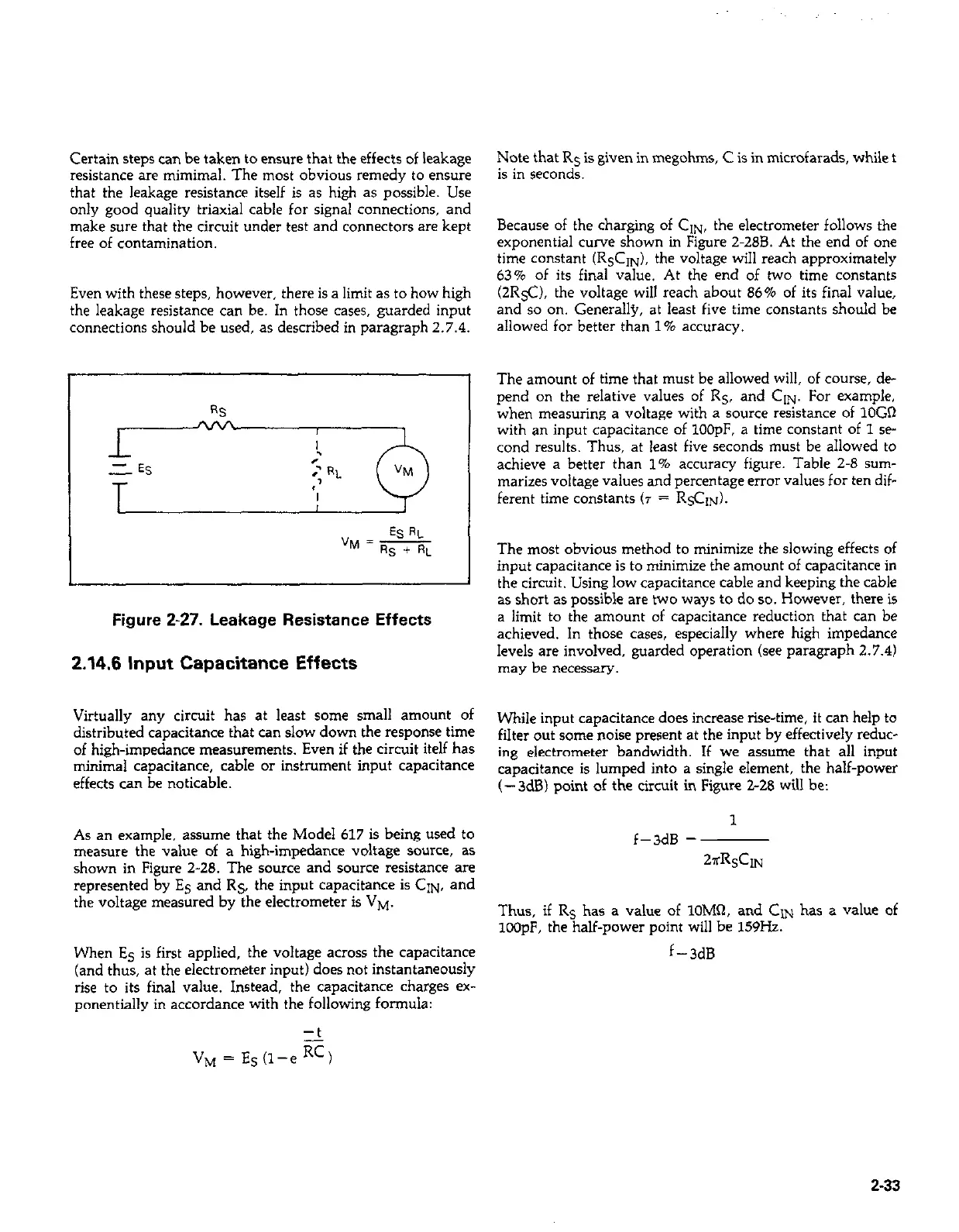
Certain steps can be taken to ensure that the effects of leakage
resistance are mimimal. The most obvious remedy to ensure
that the leakage resistance itself is as high as possible. Use
only good quality triaxial cable for signal connections, and
make sure that the circuit under test and connectors are kept
free of contamination.
Even with these steps, however, there is a limit as to how high
the leakage resistance can be. In those cases, guarded input
connections should be used, as described in paragraph 2.7.4.
ESRL
")J = -
Rs + RL
I
I
Figure Z-27. Leakage Resistance Effects
2.14.6 Input Capacitance Effects
Virtually any circuit has at least some small amount of
distributed capacitance that can slow down the response time
of high-impedance measurements. Even if the circuit itelf has
minimal capacitance, cable or instrument input capacitance
effects can be noticable.
As an example, assume that the Model 617 is being used to
measure the value of a high-impedance voltage source, as
shown in Figure 2-28. The source and source resistance are
represented by E5 and R5, the input capacitance is GIN, and
the voltage measured by the electrometer is VM.
When E5 is first applied, the voltage across the capacitance
(and thus, at the electrometer input) does not instantaneously
rise to its final value. Instead, the capacitance charges ex-
ponentially in accordance with the following formula:
Note that Rs is given in megohms, C is in microfarads, while t
is in seconds.
Because of the charging of GIN, the electrometer follows the
exponential curve shown in Figure 2.288. At the end of one
time constant (R&IN), the voltage will reach approximately
63% of its final value. At the end of two time constants
(2R5C). the voltage will reach about 86% of its final value,
and so on. Generally, at least five time constants should be
allowed for better than 1% accuracy.
The amount of time that must be allowed will, of course, de
pend on the relative values of R5, and GIN. For example,
when measuring a voltage with a source resistance of 1OGR
with an input capacitance of 100pF. a time constant of 1 se
cond results. Thus, at least five seconds must be allowed to
achieve a better than 1% accuracy figure. Table 2-8 sum-
marizes voltage values and percentage error values for ten dif-
ferent time constants (T = R$ZIN).
The most obvious method to minimize the slowing effects of
input capacitance is to minimize the amount of capacitance in
the circuit. Using low capacitance cable and keeping the cable
as short as possible are two ways to do so. However, there is
a limit to the amount of capacitance reduction that can be
achieved. In those cases, especially where high impedance
levels are involved, guarded operation (see paragraph 2.7.4)
may be necessary.
While input capacitance does increase rise-time, it can help to
filter out some noise present at the input by effectively reduc-
ing electrometer bandwidth. If we assume that all input
capacitance is lumped into a single element, the half-power
(- 3dB) point of the circuit in Figure Z-28 will be:
1
f-3dB =
~~RsCIN
Thus, if Rs has a value of lOM’J, and CON has a value of
lCOpF, the half-power point will be 159Hz.
f-3dB
2-33