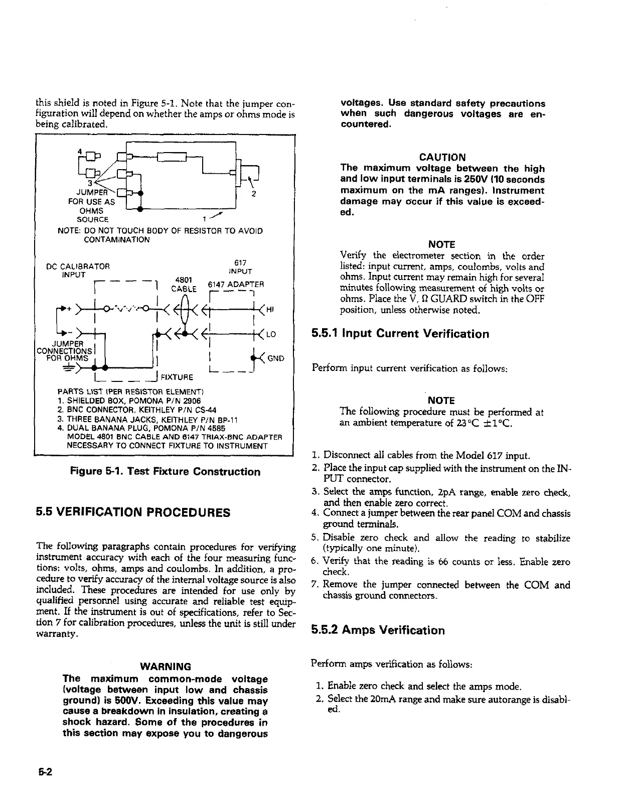
this shield is noted in Figure 5-l. Note that the jumper co”-
voltages. Use standard safety precautions
figuration will depend on whether the amps or ohms mode is
when such dangerous voltages are en-
being calibrated.
countered.
SOURCE
NOTE: DO NOT TOUCH BODY OF RESISTOR TO A”O,D
CONTAMlNATlON
DC CALIBRATOR
617
INPUT
INPUT
PARTS LIST (PER RESISTOR ELEMENT)
1. SHIELDED BOX, POMONA P/N 2906
2. BNC CONNECTOR, KEITHLEY P/N CS-W
3. THREE BANANA JACKS, KEITHLEY P/N BP-,,
4. DUAL BANANA PLUG, POMONA P/N 4585
MODEL 4801 BNC CABLE AND 6147 TRIAX-SNC ADAPTER
NECESSARY TO CONNECT FIXTVRE TO ,NSTR”MENT
CAUTION
The maximum voltage between the high
and low input terminals is 250V (IO seconds
maximum on the mA ranges). Instrument
damage may occur if this value is exceed-
ed.
NOTE
Verify the electrometer section in the order
listed: input current, amps, coulombs, volts and
ohms. Input current may remain high for several
minutes following measurement of high volts or
ohms. Place the V, 0 GUARD switch in the OFF
position, unless otherwise noted.
5.5.1 Input Current Verification
Perform input current verification as follows:
NOTE
The following procedure must be performed at
an ambient temperature of 23°C +l”C.
Figure 5-l. Test Fixture Construction
5.5 VERIFICATION PROCEDURES
The following paragraphs contain procedures for verifving
5. Disable zero check and allow the reading to stabilize
,~ . .
,tv!JlCa,,” one mmute,.
1. Disconnect all cables from the Model 617 input.
2. Place the input cap supplied with the instrument on the IN-
PUT co”“ector.
3. Select the amps function, 2pA range, enable zero check,
and then enable zero correct.
4. Connect a jumper between the rear panel COM and chassis
ground terminals.
instrument accuracy with each of the four measuring f&c: .. ’
tions: volts, ohms, amps and coulombs. In addition, a pro-
6. Verify that the reading is 66 counts or less. Enable zero
cedure to verify accuracy of the internal voltage source is also
check.
included. These procedures are intended for use only by
7. Remove the jumper connected between the COM and
qualified persomwl using accurate and reliable test equip-
chassis ground connectors.
meat. If the instrument is out of specificatiow, refer to SW-
tion 7 for calibration procedures, unless the unit is still under
warranty.
5.5.2 Amps Verification
WARNING
The maximum common-mode voltage
(voltage between input low and chassis
around) is 500V. Exceedina this value mav
Pe*onn amps verification as follows:
1. Enable zero check and select the amps mode.
2. Select the 2GmA range and make sure autorange is disabl-
Eause a breakdown in ins&ion, creating a
shock hazard. Some of the procedures in
this section may expose you to dangerous
ed
5-2