take a number of minutes for the input current to
drop within specified limits. Input current can be
verified by placing the protection cap on the IN-
PUT jack and then connecting a jumper between
the COM and chassis ground terminals. With
the instrument on the 2pA range and zero check
disabled, allow the reading to settle until the in-
strument is within specifications.
Use the following procedure to measure charge with the
Model 617.
1. Turn on the power and allow a two-hour warm up period
for rated accuracy.
2. Place the instrument in the coulombs mode by pressing the
COUL button. Set V, R GUARD to OFF.
3. To achieve rated accuracy, place the instrument on the
2COpC range and zero the instrument by enabling zerc~
check and then pressing the ZERO CORRECT button.
4. Select the desired range, or use autoranging, if desired.
5. Disable zero check. A small amount of zero check hop
(sudden change in the reading) may be observed when zero
check is disabled. If desired, enable suppress to null out
any zero check hop, which typically will be in the lo-25
count range. ’
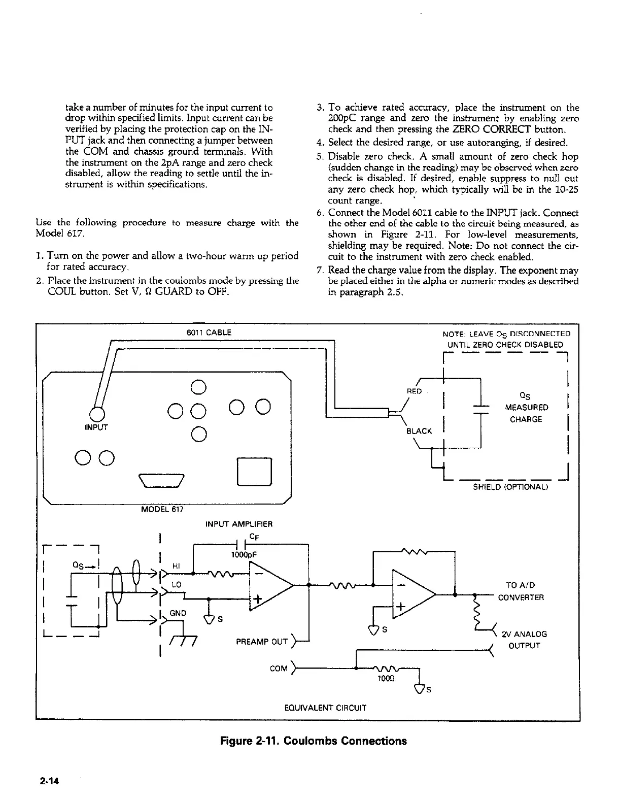
6. Connect the Model 6011 cable to the INPUT jack. Connect
the other end of the cable to the circuit being measured. as
shown in Figure 2-11. For low-level measurements,
shielding may be required. Note: Do not connect the cir-
cuit to the instrument with zero check enabled.
7. Read the charge value from the display. The exponent may
be placed either in the alpha or numeric modes as described
in paragraph 2.5.
A
0 \ RED
00
QS
MEASURED
IN;;;T
00
CHARGE
0
6011 CABLE
NOTE: LEAVE OS DISCONNECTED
“NTlL ZERO CHECK DISABLED
r----i
00
cl ---- 1
SHIELD ,OPTIONAL)
J
MODEL 617
INPUT AMPLlFlER
PREAMP OUT
TO A/D
CONVERTER
EQUIVALENT C,RCUIT
Figure 2-11. Coulombs Connections
2-14