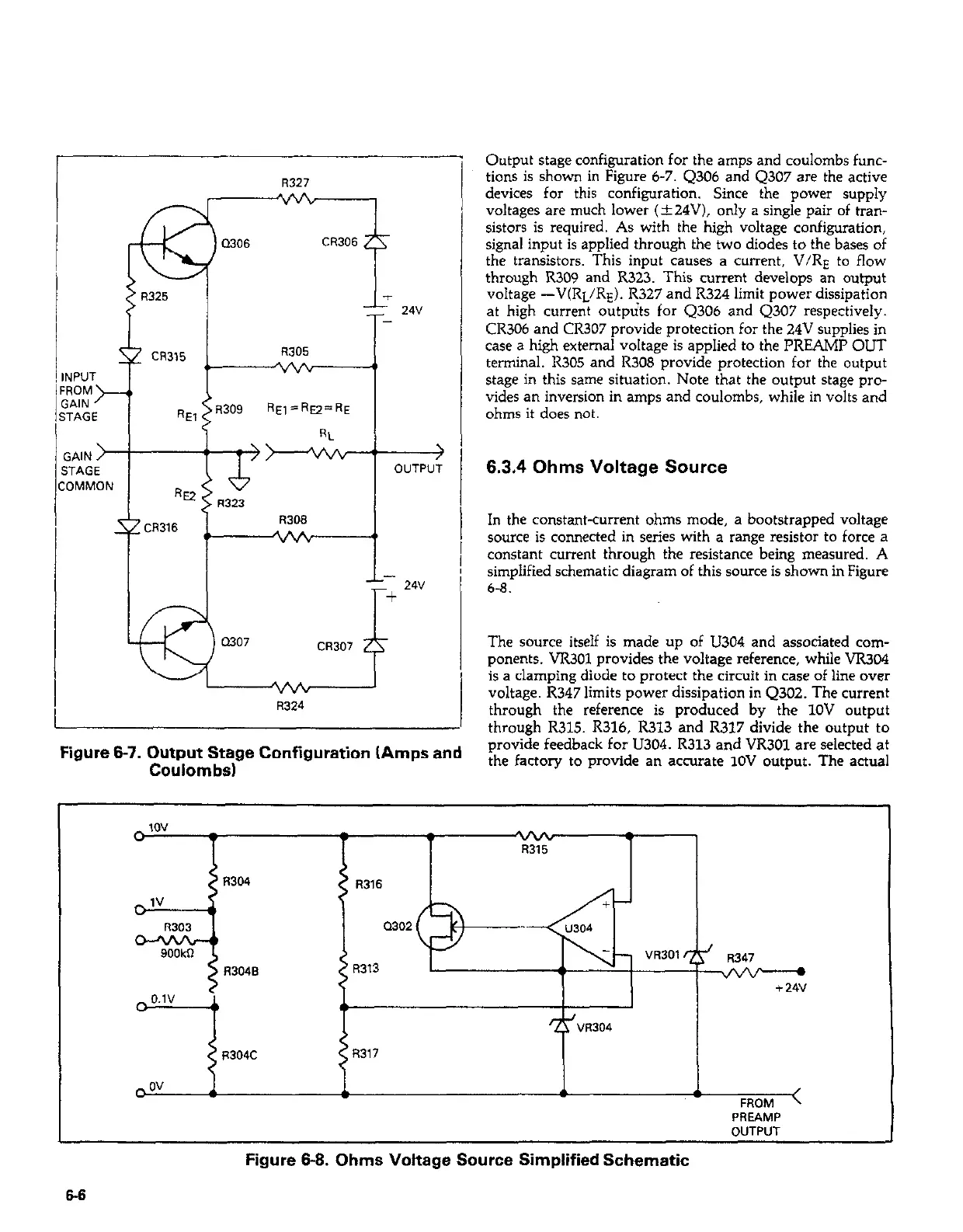
R327
, Output staze configuration for the am!x and coulombs func-
. -
tions is shown in Figure 6-7. 4306 and Q307 are the active
devices for this configuration. Since the power supply
voltages are much lower (&24V), only a single pair of tran-
sistors is required. As with the high voltage configuration,
signal input is applied through the two diodes to the bases of
the transistors. This input causes a current, V/RE to flow
through R309 and R323. This current develops an output
voltage -V(RL/RE). R327 and R324 limit power dissipation
at high current outp&s for Q306 and Q307 respectively.
CR306 and CR307 provide protection for the 24V supplies in
case a high external voltage is applied to the PREAMP OUT
terminal. R305 and R308 provide protection for the output
stage in this same situation. Note that the output stage pro-
vides an inversion in amps and coulombs, while in volts and
ohms it does not.
w
Q306
CR306 21
T
1: 24"
R305
r]PUT
-v/k
3OM
i*IN
TAGE
RE, wJ9
RE,=Ry=RE
RL
SAIN
>F--Qvv :’
)
TAGE
OUTPUT
3MMON
k2
R323
xZCR316
R308
1
“vu
-
L 24v
+
Q307
CR307 zy
vvb
R324
6.3.4 Ohms Voltage Source
In the constant-current ohms mode, a bootstrapped voltage
source is connected in series with a range resistor to force a
constant current through the resistance being measured. A
simplified schematic diagram of this source is shown in Figure
6-8.
The source itself is made up of U304 and associated com-
ponents. W.301 provides the voltage reference, while VR304
is a clamping diode to protect the circuit in case of line over
voltage. R347 limits power dissipation in Q302. The current
through the reference is produced by the 1OV output
through R315. R316, R313 and R317 divide the output to
Figure 8-7. Output Stage Configuration (Amps and
provide feedback for U304. R313 and VR301 are selected at
Coulombs)
the factory to provide an accurate 1OV output. The actual
c ov
J i
i
J
FROM <
PREAMP
OUTPUT
Figure 6-8. Ohms Voltage Source Simplified Schematic