5.5.4 Volts Verification
NOTE
Current and charge verification must be per-
formed before volts verification.
Verify the volts function as follows:
1. Enable zero check and select the volts functions with the
associated front panel buttons.
2. Select the 200mV range and enable zero correct. Check to
see that the display shows ooO.00 fl count. If not, enable
zero correct.
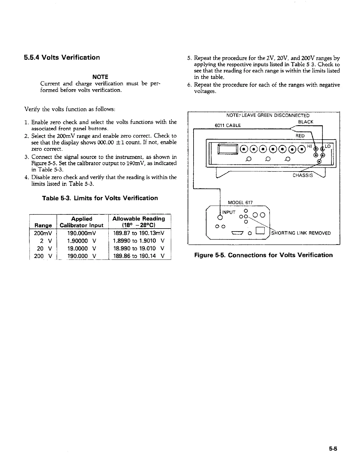
3. Connect the signal source to the instrument, as shown in
Figure 5-5. Set the calibrator output to 190mV, as indicated
in Table 5-3.
4. Disable zero check and verify that the reading is within the
limits listed in Table 5-3.
Table 53. Limits for Volts Verification
Applied
Allowable Reading
Range Calibrator Input
I180 -28W
200mV 190.000mV
189.87 to 190.13mV
2 v 1.90000 v 1 .I?990 to 1.9010 v
20 v 19.0000 v 18.990 to 19.010 V
200 v 190.000 v 189.86 to 190.14 V
5. Repeat the procedure for the ZV, ZOV, and 200V ranges by
applying the respective inputs listed in Table 5-3. Check to
see that the reading for each range is within the limits listed
in the table.
6. Repeat the procedure for each of the ranges with negative
NOTE? LEAVE GREEN DISCONNECTED
SHORTING LINK REMOVED LINK REMOVED
\
MODEL 617
/
Figure 5-5. Connections for Volts Verification
5-5