EasyManua.ls Logo

Keithley 617 User Manual

Keithley 617
183 pages
To Next Page IconTo Next Page
To Previous Page IconTo Previous Page
Page #81 background imageLoading...
Page #81 background image
Gl =Send reading without prefix. Example: -l.Z3456E+OO
GZ=Send reading with prefix and suffix when in BI (data
store) mode. Example:
NDCV-1.23456E+OO,023. In this example, memory loca-
tion 23 is being accessed.
Upon power up, or after the instrument receives a DCL or
SDC command, the instrument will be in the GO mode.
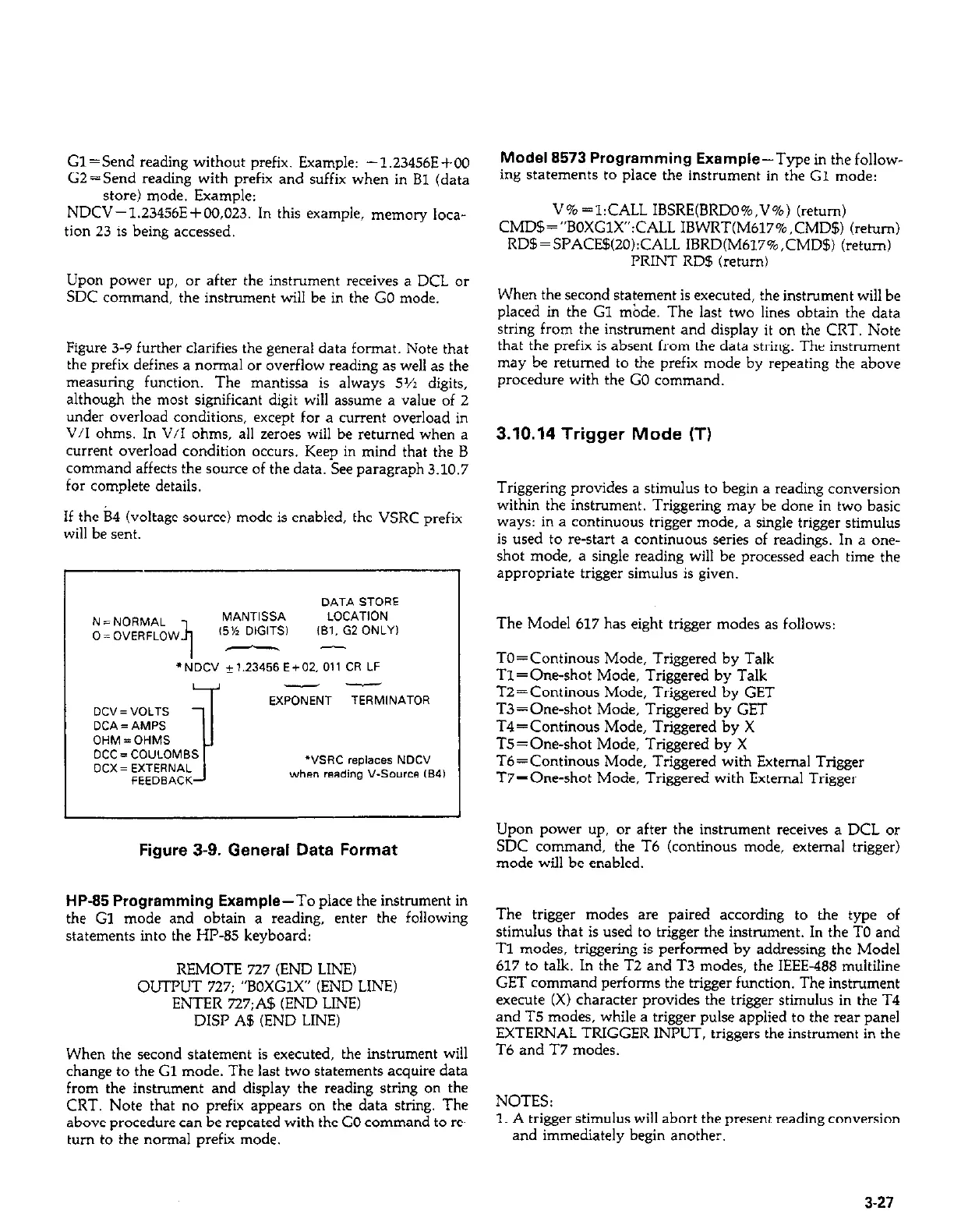
Figure 3-9 further clarifies the general data format. Note that
the prefix defines a normal or overflow reading as well as the
measuring function. The mantissa is always 5~2 digits,
although the most significant digit will assume a value of 2
under overload conditions, except for a current overload in
V/I ohms. In V/I ohms, all zeroes will be returned when a
current overload condition occurs. Keep in mind that the B
command affects the source of the data. See paragraph 3.10.7
for complete details.
If the B4 (voltage source) mode is enabled, the VSRC prefix
will be sent.
DATA STORE
I
N = NCIRMAL
II
MANTISSA
LOCATION
0 = OVERFLOW
(5% DIGITS1
,B,. G2 ONLY,
I
I
--
“NE” *1.23456 E+m. 011 CR LF
4
--
I
EXPONENT TERMlNATOR
DC”= VOLTS
DCA = AMPS
OHM=OHMS
DCC = CO”LOMBS
DCX= EXTERNAL
““SW replaces NDC”
when reading V-Source CB4)
Figure 3-9. General Data Format
HP-85 Programming Example-To place the instrument in
the Gl mode and obtain a reading, enter the following
statements into the HP-85 keyboard:
REMOTE 727 (END LINE)
OUTPUT 727; “BOXGlX” (END LINE)
ENTER 727;A$ (END LINE)
DISP A5 (END LINE)
When the second statement is executed, the instrument will
change to the Cl mode. The last two statements acquire data
from the instrument and display the reading string on the
CRT. Note that no prefix appears on the data string. The
above procedure can be repeated with the GO command to re-
turn to the normal prefix mode.
Model 8573 Programming Example-Type in thefollow-
ing statements to place the instrument in the G1 mode:
V% =l:CALL IBSRE(BRDO%,V%) (return)
CMD$=“BOXGlX”:CALL IBWRT(M617%,CMD$) (return)
RDB=SPACE5(2O):CALL IBRD(M617%,CMD$) (return)
PRINT RD5 (return)
When the second statement is executed, the instrument will be
placed in the Gl &de. The last two lines obtain the data
string from the instrument and display it on the CRT. Note
that the prefix is absent from the data string. The instrument
may be returned to the prefix mode by repeating the above
procedure with the GO command.
3.10.14 Trigger Mode (T)
Triggering provides a stimulus to begin a reading conversion
within the instrument. Triggering may be done in two basic
ways: in a continuous trigger mode, a single trigger stimulus
is used to restart a continuous series of readings. In a one-
shot mode, a single reading will be processed each time the
appropriate trigger simulus is given.
The Model 617 has eight trigger modes as follows:
TO=Continous Mode, Triggered by Talk
Tl =One-shot Mode, Triggered by Talk
T2=Continous Mode, Triggered by GET
T3 = One-shot Mode, Triggered by GET
T4=Continous Mode, Triggered by X
T5=Oreshot Mode, Triggered by X
Tb=Continous Mode, Triggered with External Trigger
Ti’=One-shot Mode, Triggered with External Trigger
Upon power up, or after the instrument receives a DCL or
SDC command, the T6 (continous mode, external trigger)
mode will be enabled.
The trigger modes are paired according to the type of
stimulus that is used to trigger the instrument. In the TO and
Tl modes, triggering is performed by addressing the Model
617 to talk. In the T2 and T3 modes, the IEEE-488 multiline
GET command performs the trigger function. The instrument
execute (X) character provides the trigger stimulus in the T4
and T5 modes, while a trigger pulse applied to the rear panel
EXTERNAL TRIGGER INPUT, triggers the instrument in the
T6 and T7 modes.
NOTES:
1. A trigger stimulus will abort the present reading conversion
and immediately begin another.
3-27

Table of Contents

Other manuals for Keithley 617

Question and Answer IconNeed help?

Do you have a question about the Keithley 617 and is the answer not in the manual?

Keithley 617 Specifications

General IconGeneral
BrandKeithley
Model617
CategoryMeasuring Instruments
LanguageEnglish

Summary

Warranty Information

Warranty

Details the warranty terms and conditions for the product and specific components.

Specifications

Specifications

Details the electrical and performance specifications for the Model 617 electrometer.

Safety Precautions

Safety Precautions

Advises on essential safety measures to avoid injury and instrument damage during operation.

Section 1: General Information (Continued)

Unpacking and Getting Started

Details unpacking, inspection, and initial steps to operate the Model 617.

Section 2: Operation

2.2 Power Up Procedure

Details the steps for connecting power and turning on the instrument.

2.3 Power Up Self Test and Display Messages

Explains the self-test routine and potential display messages upon startup.

Section 2: Operation (Continued)

2.4 Front Panel Familiarization

Provides an overview of the Model 617's front panel layout, controls, and indicators.

2.7 Basic Measurement Techniques

Introduces fundamental procedures for making voltage, resistance, charge, and current measurements.

2.7.2 Input Connections

Details how to connect input signals to the rear panel INPUT connector.

2.7.4 Guarded Operation

Explains the concept and application of guarding to minimize leakage and improve measurements.

2.7.5 Making Current Measurements

Details the procedure for measuring low-level currents, including picoampere ranges.

2.7.6 Making Charge Measurements

Describes how to measure charge using the Model 617's coulombs ranges.

2.7.7 Resistance Measurements

Explains how to measure resistance using constant current and voltage methods.

2.8 Using The Voltage Source

Explains how to use the Model 617's built-in voltage source for V/I measurements.

2.10 Using External Feedback

Explains how to extend capabilities using external feedback networks.

2.11 Using Zero Correct and Baseline Suppression

Covers instrument offset cancellation and baseline value storage.

2.11.2 Using Suppression

Details how to store an offset value and subtract it from subsequent readings.

2.13 External Triggering

Explains how to trigger the instrument using external BNC connectors.

2.4.1 Controls

Describes the function and operation of each front panel control button.

2.5.3 Calibration

Introduces the digital calibration program for front panel or IEEE-488 bus use.

2.7.3 Making Voltage Measurements

Provides step-by-step instructions for measuring DC voltages with the Model 617.

2.8.1 Basic Operating Procedure

Guides on connecting and adjusting the voltage source output.

2.11.1 Zero Correct and Zero Check

Explains how to use Zero Correct and Zero Check to cancel internal offsets.

2.12 Data Storage

Describes the internal 100-point data store mode for logging readings.

2.13.1 External Trigger

Details continuous and one-shot triggering modes via the external trigger input.

2.14 Measurement Considerations

Discusses factors affecting measurements at low signal levels.

2.8.2 V/I Resistance Measurements

Describes how to measure high resistances using the voltage source and electrometer.

Section 3: IEEE-488 Programming

Section 3: IEEE-488 Programming (Continued)

3.4 Bus Commands

Covers device commands, grouped into uniline, multiline, and device-dependent categories.

3.7.2 Bus Connections

Details how to connect the Model 617 to the IEEE-488 bus using appropriate cables.

3.7.3 Primary Address Programming

Explains how to check and set the instrument's primary address for bus communication.

3.8 Software Considerations

Discusses software aspects for IEEE-488 controllers like HP-85 and IBM-PC.

3.9 General Bus Command Programming

Covers general bus commands like DCL, REN, IFC, LLO, GTL, SDC, GET, SPE, SPD.

3.10 Device-Dependent Command Programming

Details commands controlling modes like function, range, trigger, and data format.

3.10.2 Function (F)

Describes commands to select measurement functions like Volts, Amps, Ohms, Coulombs.

3.10.3 Range (R)

Explains commands for controlling instrument sensitivity and selecting measurement ranges.

3.10.4 Zero Correct and Zero Check (Z and C)

Details commands for canceling internal offsets and zeroing the instrument.

3.10.5 Baseline Suppression (N)

Explains commands to store an offset and subtract it from subsequent readings.

3.10.9 Voltage Source Value (V)

Details commands for programming the built-in voltage source output.

3.4.5 Device-Dependent Commands

Describes commands specific to device configuration, controlling functions like mode and range.

3.10.8 Data Store Mode

Explains how to use the data store for logging readings and setting intervals.

3.10.11 Calibration Value (A)

Describes commands for setting calibration values for ranges and functions.

Section 4: Applications

4.2 Insulation Resistance Measurements

Details how to measure high insulation resistances using constant current and voltage methods.

Section 4: Applications (Continued)

4.3 High Impedance Voltmeter

Explains using the Model 617 as a high-impedance voltmeter with minimal circuit loading.

4.4 Low-Level Leakage Current Measurements

Guides on measuring low-level currents like nanoamperes and picoamperes.

Section 5: Performance Verification

Section 5: Performance Verification (Continued)

5.5 Verification Procedures

Provides detailed procedures for verifying accuracy of volts, ohms, amps, and coulombs functions.

Section 7: Maintenance

Section 7: Maintenance (Continued)

7.4.5 Front Panel Calibration

Provides step-by-step instructions for calibrating from the front panel.

7.4.11 Amps Calibration

Provides calibration steps for the amps function across various ranges.

7.4.12 Coulombs Calibration

Details the procedure for calibrating the coulombs function.

7.4.14 Ohms Calibration

Provides calibration steps for the ohms function across various ranges.

7.4.15 Voltage Source Calibration

Details the procedure for calibrating the instrument's internal voltage source.

7.4 Calibration

Introduces digital calibration capabilities and recommendations.

7.4.6 IEEE-488 Bus Calibration

Details procedures for calibrating the instrument via the IEEE-488 bus using a computer.

7.4.8 Input Offset Adjustment

Describes steps to null any small offset in the input amplifier.

7.4.13 Volts Calibration

Outlines the calibration steps for the volts function across different ranges.

7.7 Troubleshooting

Offers guidance for diagnosing and resolving instrument problems.

7.4.9 Input Current Adjustment

Details procedures to null input current in the input stage for temperature compensation.

Related product manuals