2. The front panel TRIG button will trigger the instrument
regardless of the selected trigger mode, unless LLO is in ef-
fect.
3. Serial polling usually addresses the instrument to talk. This
talk command will trigger the instrument in the TO and Tl
modes.
HP-85 Programming Example-Place the instrument in
the one-shot on talk mode with the following statements:
REMOTE 727 (END LINE)
OUTPUT 727:“TlX” (END LINE)
One reading can now be triggered and the resulting data ob-
tained with the following statements:
ENTER 727;A!$ (END LINE)
DISP A$ (END LINE)
In this example, the ENTER statement addresses the Model
617 to talk, at which point a single reading is triggered. When
the reading has been processed (360msec later), it is sent out
over to the bus to the computer, which then displays the
result.
Model 8573 Programming Example--Place the instru-
ment in the Tl mode with the following statements:
V%=l:CALL IBSRE(BRDO%,V%) (return)
CMD$=“TlX”:CALL IBWRT(M617%,CMD$) (return)
The instrument can now be addressed to talk to trigger a con-
version, and the resulting data displayed with the following
statements:
RD$=SPACE$(20):CALL IBRD(M617%,RD$) (return)
PRINT RD$ (return)
Each time the IBRD function is called, the instrument is ad-
dressed to talk, at which time it is triggered. When the con-
version is complete (360msec later), the reading is sent out
over the bus to the computer, which then displays the result-
ing data.
3.10.15 SRQ Mask IM) and Status Byte Format
The SRQ command controls which of a number of conditions
within the Model 617 will cause the instrument to request ser-
vice from the controller by asserting SRQ. Once an SRQ is
generated, the status byte can be checked to determine if the
Model 617 was the instrument that asserted SRQ, and, if so,
what conditions caused it to do so. Note that additional data
and error conditions can be checked by using the Ul and U2
commands, as described in paragraph 3.10.18.
3.28
The Model 617 can be programmed to generate an SRQ
under one or more of the following conditions:
1. If an overrange condition occurs.
2. When the data store memory is full (100 readings).
3. If a reading is completed.
4. When the instrument is ready to accept bus commands.
5. If an error occurs. The nature of the error can then be
determined with the Ul command, as described in
paragraph 3.10.18 (use Ul to restore SRQ after an error
occlm )
Upon power up, or after a DCL or SDC command is re-
ceived, SRQ is disabled.
SRQ Mask-The Model 617 uses an internal mask to deter-
mine which conditions will cause an SRQ to be generated.
Figure 3-10 shows the general format of this mask, which is
made up of eight bits. The SRQ has the same general format
as the status byte (described below) except for the fact that bit
6 is not used in the SRQ mask.
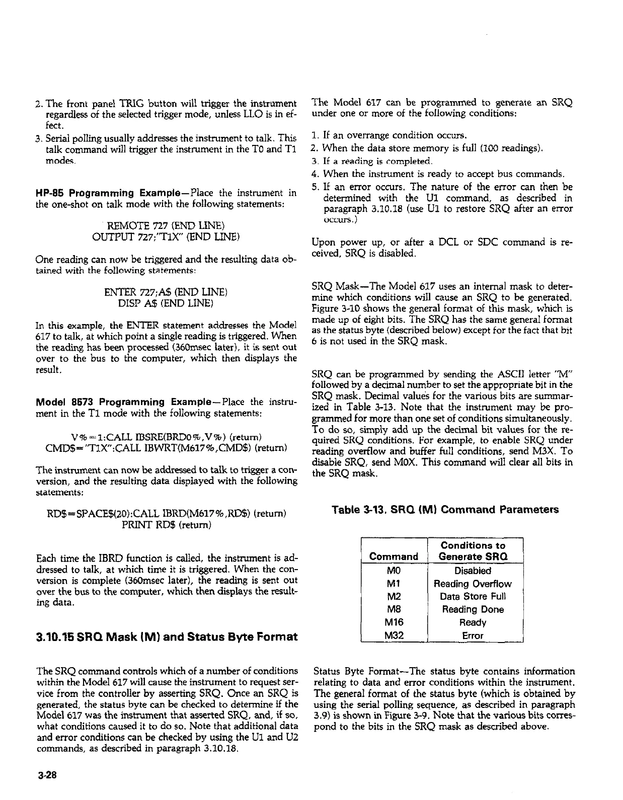
SRQ can be programmed by sending the ASCII letter “M”
followed by a decimal number to set the appropriate bit in the
SRQ mask. Decimal valu&s for the various bits are sununar-
ized in Table 3-13. Note that the instrument may be pro-
grammed for more than one set of conditions simultaneously.
To do so, simply add up the decimal bit values for the re-
quired SRQ conditions. For example, to enable SRQ under
reading overflow and buffer full conditions, send M3X. To
disable SRQ, send MOX. This command will clear all bits in
the SRQ mask.
Table 3-13. SRQ (MI Command Parameters
T
Reading Overflow
Data Store Full
Status Byte Format-The status byte contains information
relating to data and error conditions within the instrument.
The general format of the status byte (which is obtained by
using the serial polling sequence, as described in paragraph
3.9) is shown in Figure 3-9. Note that the various bits cor~es-
pond to the bits in the SRQ mask as described above.