!
I= ROS BY 617
-I
lSTAT”S BYTE ONLY)
I= ERROR
IA
I
1 =REAOING
OVERFLOW
1 = DATA STORE
1= READY I= READING DONE
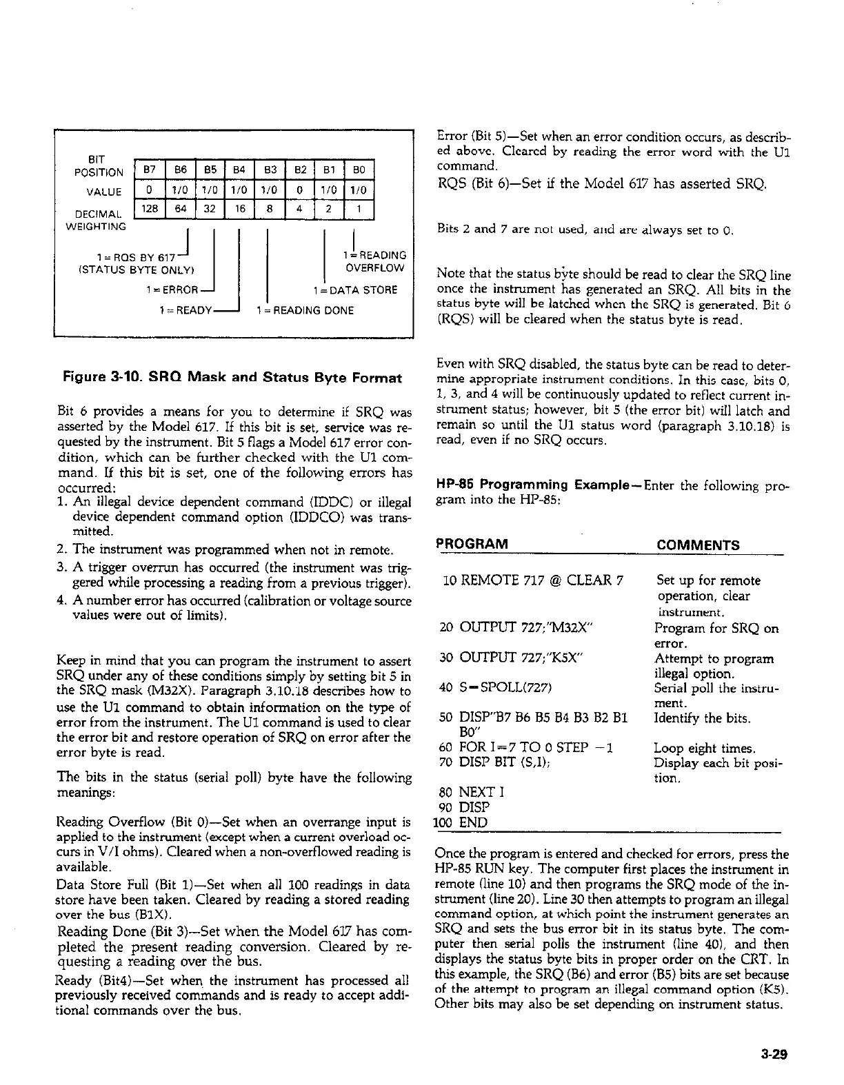
Figure 3-10. SRQ Mask and Status Byte Format
Bit 6 provides a means for you to determine if SRQ was
asserted by the Model 617. If this bit is set, service was re-
quested by the instrument. Bit 5 flags a Model 617 error con-
dition, which can be further checked with the Ul corn-
mand. If this bit is set, one of the following errors has
occurred:
1. An illegal device dependent command (IDDC) or illegal
device dependent command option (IDDCO) was trans-
mitted.
2. The instrument was programmed when not in remote.
3. A trigger overrun has occurred (the instrument was trig-
gered while processing a reading from a previous trigger).
4. A number error has occurred (calibration or voltage source
values were out of limits).
Keep in mind that you can program the instrument to assert
SRQ under any of these conditions simply by setting bit 5 in
the SRQ mask (M32X). Paragraph 3.10.18 describes how to
use the Ul command to obtain information on the type of
error from the instrument. The LJl command is used to clear
the error bit and restore operation of SRQ on error after the
error byte is read.
The bits in the status (serial poll) byte have the following
meanings:
Reading Overflow (Bit O&Set when an overrange input is
applied to the instrument (except when a current overload oc-
curs in V/I ohms). Cleared when a non-overflowed reading is
available.
Data Store Full (Bit 1)-&t when all 1OO readings in data
store have been taken. Cleared by reading a stored reading
over the bus (B1X).
Reading Done (Bit 3)--S& when the Model 6l7 has com-
pleted the present reading conversion. Cleared by re-
questing a reading over the bus.
Ready (Bit4)-Set when. the instrument has processed all
previously received commands and is ready to accept addi-
tional commands over the bus.
Error (Bit 5)-Set when an error condition occurs, as describ-
ed above. Cleared by reading the error word with the U1
command.
RQS (Bit 6)--S& if the Model 617 has asserted SRQ.
Bits 2 and 7 are not used, and are always set to 0.
Note that the status bite should be read to clear the SRQ line
once the instrument has generated an SRQ. All bits in the
status byte will be latched when the SRQ is generated. Bit 6
(RQS) will be cleared when the status byte is read.
Even with SRQ disabled, the status byte can be read to deter-
mine appropriate instrument conditions. In this case, bits 0,
1, 3, and 4 will be continuously updated to reflect current in-
strument status; however, bit 5 (the error bit) will latch and
remain so until the U1 status word (paragraph 3.10.18) is
read, even if no SRQ occurs.
HP-85 Programming Example-Enter the following pro-
gram into the HP-85:
PROGRAM
COMMENTS
10 REMOTE 717 @ CLEAR 7
20 OUTPUT 727;“M32X”
30 OUTPUT 727;“KSX”
set up for remote
operation, clear
instrument.
Program for SRQ on
error.
Attempt to program
40 S = SPOLL(727)
illegal option.
Serial poll the instru-
ment.
50 DISP”B7 B6 85 84 83 B2 Bl
Identify the bits.
RW’
60 %R 1=7TO 0 STEP -1
70 DISP BIT (S.1):
80 NEXT I
90 DISP
100 END
Loop eight times.
Display each bit posi-
tion.
Once the program is entered and checked for errors, press the
HP-85 RUN key. The computer first places the instrument in
remote (line 10) and then programs the SRQ mode of the in-
strument (line 20). Line 30 then attempts to program an illegal
command option, at which point the instrument generates an
SRQ and sets the bus error bit in its status byte. The com-
puter then serial polls the instrument (line 40). and then
displays the status byte bits in proper order on the CRT. In
this example, the SRQ (B6) and error (B5) bits are set because
of the attempt to program an illegal command option (KS).
Other bits may also be set depending on instrument status.
3-29