+‘MV IEOOTSTRAPPEDI
+5v -4vv-- -5”
BOOTSTRAPPEI
BOOTSTRAPPED
GROUND
m TO GAIN
0
> STAGE
R33.5
R336
-5V IBOOTSTRAPPEDI
Figure 6-4. Simplified Schematic of Input Stage
-
c319
FQOM
INPUT
49
-u309
TO OUTPUT
STAGE
+
STAGE
-
Figure 6-5. Gain Stage
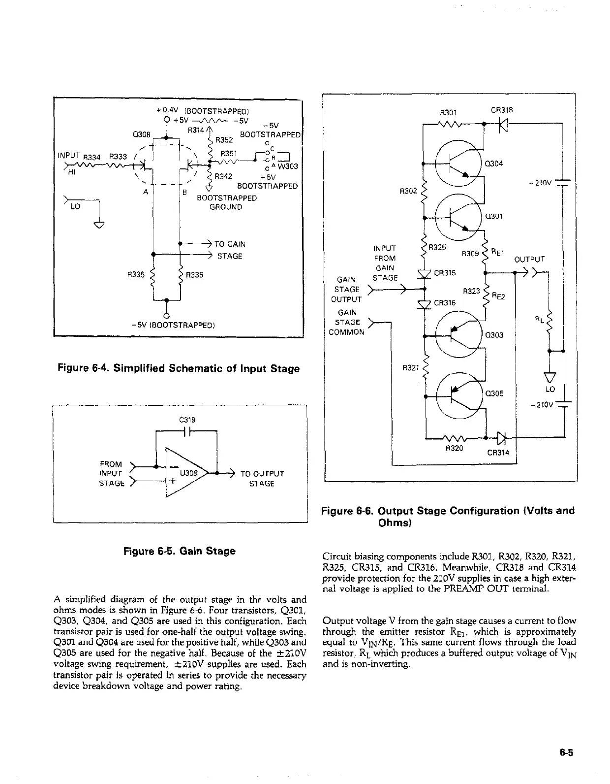
A simplified diagram of the output stage in the volts and
ohms modes is shown in Figure 6-6. Four transistors, Q301,
4303, Q304, and Q305 are used in this configuration. Each
transistor pair is used for one-half the output voltage swing.
Q301 and Q304 are used for the positive half, while Q303 and
Q305 are used for the negative half. Because of the rt21OV
voltage swing requirement, &21OV supplies are used. Each
transistor pair is operated in series to provide the necessary
device breakdown voltage and power rating.
GAIN
STAGE
R301
CR318
iNPUT
FROM
OUTPUT
OUTPUT ’
GAIN
STAGE j---
:OMMON
R321
Figure 6-6. Output Stage Configuration (Volts and
Ohms)
Circuit biasing components include R301, R302, R320, R321,
R325, CR315, and CR316. Meanwhile, CR318 and CR314
provide protection for the 210V supplies in case a high exter-
nal voltage is applied to the PREAh4P OUT terminal.
Output voltage V from the gain stage causes a current to flow
through the emitter resistor REP, which is approximately
equal to VIN/RE. This same current flows through the load
resistor, RL which produces a buffered output voltage of VIN
and is non-inverting.
6-5