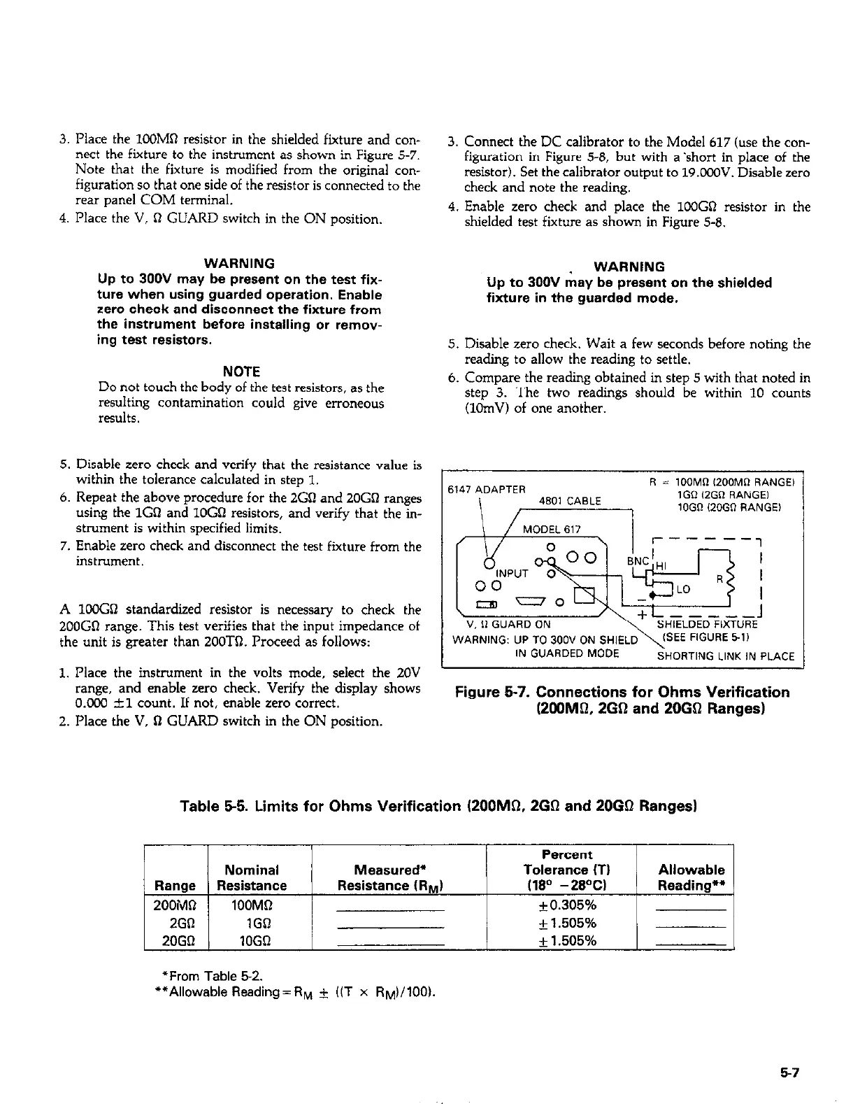
3. Place the lOOMa resistor in the shielded fixture and con-
nect the fiiture to the instrument as shown in Figure 5-7.
Note that the fixture is modified from the original con-
figuration so that one side of the resistor is connected to the
rear panel COM terminal.
4. Place the V, R GUARD switch in the ON position.
WARNING
Up to 300V may be present on the test fix-
ture when using guarded operation, Enable
zero check and disconnect the fixture from
the instrument before installing or remov-
ing test resistors.
NOTE
Do not touch the body of the test resistors, as the
resulting contamination could give erroneous
results.
5. Disable zero check and verify that the resistance value is
within the tolerance calculated in step 1.
6. Repeat the above procedure for the 2Gn and 20Gn ranges
using the 1CX and lOGa resistors, and verify that the in-
strument is within specified limits.
7. Enable zero check and disconnect the test fixture from the
instrument.
A lOOGo standardized resistor is necessary to check the
200GQ range. This test verifies that the input impedance of
the unit is greater than 2OOTQ. Proceed as follows:
1. Place the instrument in the volts mode, select the 20V
range, and enable zero check. Verify the display shows
O.CCO zkl count. If not, enable zero correct.
2. Place the V, 0 GUARD switch in the ON position.
3. Connect the DC calibrator to the Model 617 (use the con-
figuration in Figure 5-8, but with a ‘short in place of the
resistor). Set the calibrator output to 19.OOS’. Disable zero
check and note the reading.
4. Enable zero check and place the 1OOGQ resistor in the
shielded test fixture as shown in Figure 5-8.
WARNING
Up to 300V may be present on the shielded
fiaure in the guarded mode.
5. Disable zero check. Wait a few seconds before noting the
reading to allow the reading to settle.
6. Compare the reading obtained in step 5 with that noted in
step 3. The two readings should be within 10 counts
(10mV) of one another.
6147 ADAPTER
R = IOOMR ,200MR RANGE)
4801 CABLE
IGR 12GR RANGE,
lOGO,20GO RANGEI
“. 0 GUARD ON
WARNING: UP TO 300” ON SHIELD\= FIGURE 5-1)
IN GUARDED MODE
SHORTING LINK IN PLACE
Figure 5-7. Connections for Ohms Verification
(2OOMQ. 2GQ and 2003 Ranges)
Table 5-5. Limits for Ohms Verification (200M0, 260 and 2OGQ Ranges)
Percent
Nominal Measured*
Tolerance (TI Allowable
Range
Resistance Resistance (RrJ (180 -2gw Reading**
200MQ 1OOMD + 0.305%
I I
2Gfl 1GO
+ 1.505%
20GQ 1OGl-I
* 1.505%
*From Table 52.
**Allowable Reading=RM i (CT x R~)/100l.
57