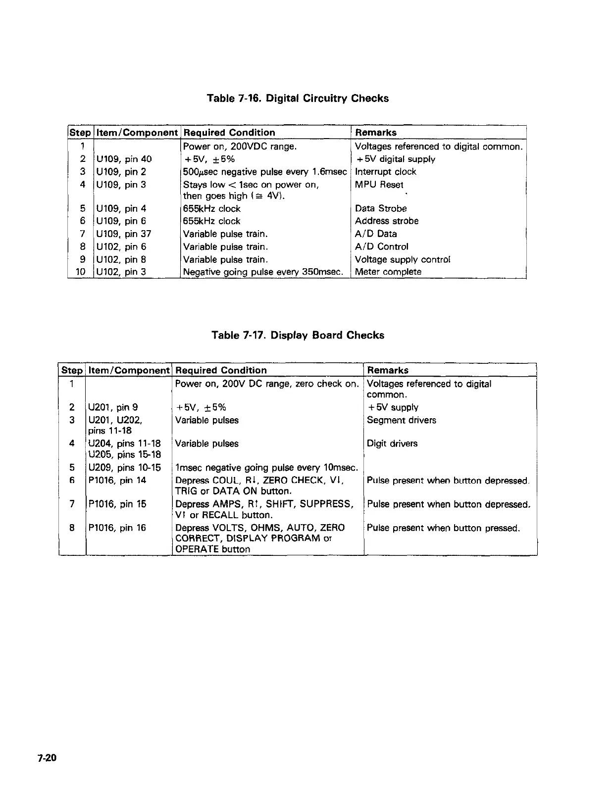
Table 7-16. Digital Circuitry Checks
Step 1 Item/Component 1 Required Condition
1
2 U109, pin 40
3 U109, pin 2
4 U109, pin 3
5 U109, pin 4
6 UlO9, pin 6
7 UlO9. pin 37
8 U102, pin 6
9 U102, pin 8
10 U102, pin 3
Power on, 200VDC range.
+5v, +5%
500pec negative pulse every 1.6msec
Stays low < lsec on power on,
then goes high (z 4V).
655kHz clock
655kHz clock
Variable pulse train.
Variable pulse train.
Variable pulse train.
Negative going pulse every 350msec.
Voltages referenced to digital common.
ri
Data Strobe
Address strobe
AID Data
AID Control
Voltage supply control
Meter complete
Table 7-17. Display Board Checks
Step Itam/Component Required Condition
Remarks
1
Power on, 200V DC range, zero check on. Voltages referenced to digital
comma”.
2 U201, pin 9
+5v, +_5% + 5v supply
3 u201, u202,
Variable pulses
Segment drivers
pins 1 l-18
4 U204, pins 11-18 Variable pulses
Digit drivers
U205. oins 15-18
5 U209; bins lo-15
lmsec negative going pulse every 10msec.
6 P1016, pin 14 Depress COUL, R1, ZERO CHECK, VI,
Pulse present when button depressed.
TRIG or DATA ON button.
7 P1016, pin 15 Depress AMPS, RI, SHIFT, SUPPRESS,
Pulse present when button depressed.
VI or RECALL button.
8 P1016, pin 16
Depress VOLTS, OHMS, AUTO, ZERO
Pulse present when button pressed.
CORRECT, DISPLAY PROGRAM or
OPERATE button
720