Volts Verification
NOTE
Current and charge verification must be performed
before volts verification.
Connect the Model 617 and 19OV calibration source to the
Model 263 as shown in Figure 2, and perform volts verifica-
tion as follows:
1. On the Model 617, enable zero check and select the
200mV range.
2. Check to see that the display reads 000.00 k1 count.
If not, enable zero correct.
3. Program the Model 263 to output 19O.OOOmV
4. Disable zero check and verify that the reading on the
Model 617 is within the liits listed in Table 2.
5. Using Table 2 as a guide, repeat steps 1 through 4 for
the 2V and 2W ranges.
6. Set the Model 617 to the 200V range.
7. Set the external calibration source to output 19O.OOOV
to the Model 263.
8. Source 19O.OOOV to the Model 617 by pressing SHIFT
VOLTS on the Model 263.
9. Verify that the reading on the Model 617 is within the
limits listed in the table.
10. Enable zero check on the Model 263 and turn off the
external calibration (19OV) source.
Ohms Verification
Connect the Model 617 to the Model 263 as shown in
Figure 3 and perform ohms verification as follows:
NOTE
Chazge and current verification must be performed
before resistance verification.
1. Set the Model 617 to the 2k62 range.
2. Zero correct the Model 637 by enabling zero check and
zero correct in that order.
3. Set the Model 26.3 to the lkQ range, and while in
OPERATE, press ZERO to source zero ohms to the
Model 617.
4. Release zero check on the Model 617 and allow the
reading to settle.
5. On the Model 617, press SUPPRESS to cancel offset
and test lead resistance.
6. On the Model 263, source the lk0 resistor to the Model
6lZ The actual value of the output resistance is
displayed on the Model 263.
7. Record the reading on the Model 263 in Table 3.
8. Calculate the Model 617 reading limit using the formula
in the table.
9. Verify that the reading on the Model 617 equals the
Model 263 reading + to calculated limit.
10. Referring to Table 3, repeat the basic procedure in steps
3 through 9 for the 20kQ range.
11. For the remaining Model 617 ranges, repeat steps 6
through 9 by sourcing the appropriate resistances to
the electrometer. Note that guard must be enabled on
both the Models 617 and 263 when verifying the GQ
ranges. Also, note that COM of the Model 6l7 must
be connected to COMMON of the Model 263 (see
Figure 3).
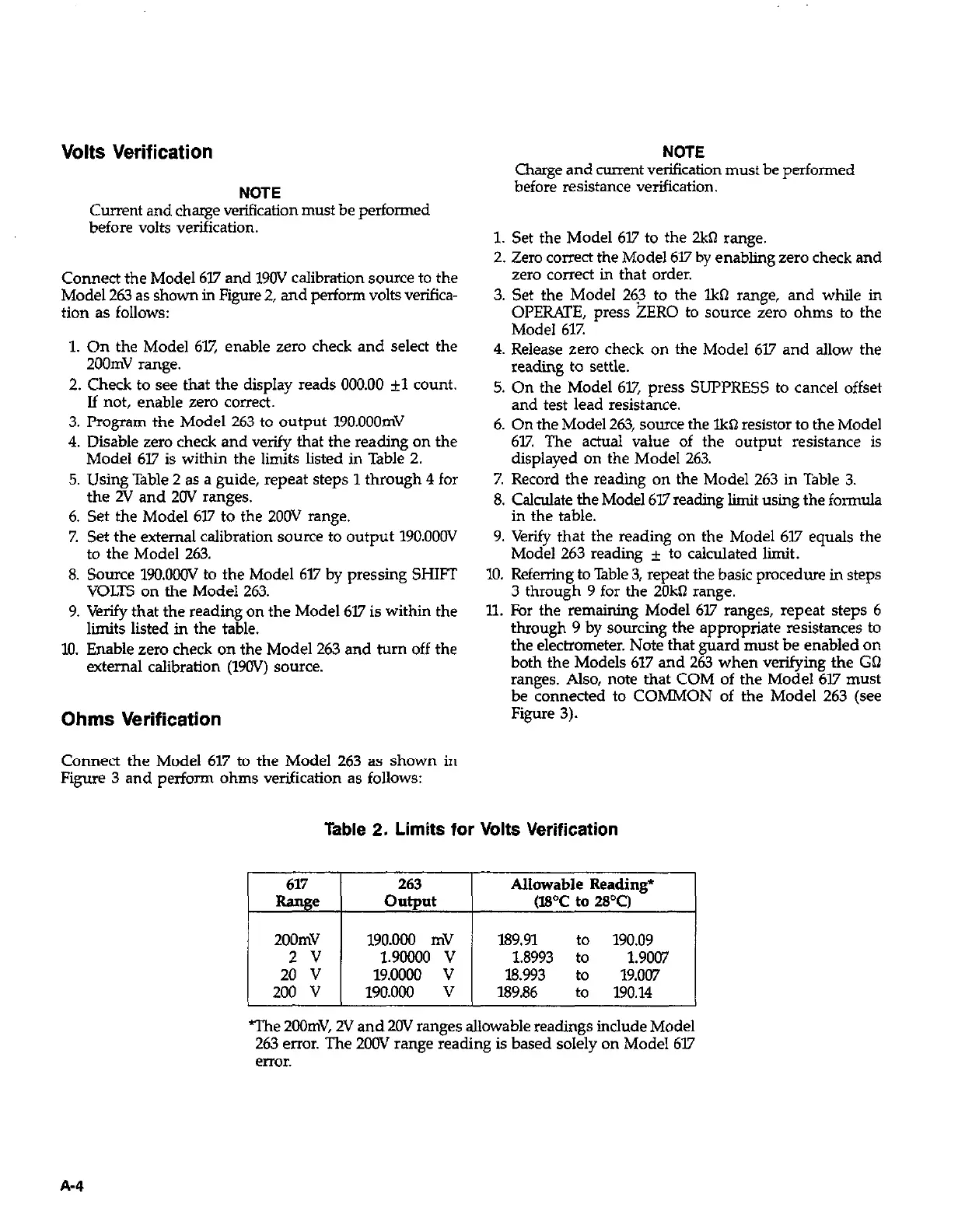
Table 2. Limits for Volts Verification
617
Range
263
output
Allowable Reading*
(WC to 2Pcl
200mV 19O.OCHl mV
2v 1.90000 v
189.91 :: 190.09
1.8993 1.9007
20 v 19.0000 v 18.993 to 19.007
200 v 190.000 v 189.86 to 190.14
The 2oOmV, 2V and 20V ranges allowable readings include Model
263 error. The 200V range reading is based solely on Model 617
enor.