Use the following procedure to measure resistance with this
mode:
1. Turn on the instrument and allow it to warm up for one
hour to obtain rated accuracy.
2. Place the instrument in the amps mode by pressing AMPS.
3. For maximum accuracy, select the 2pA range and zero COT-
rect the instrument by enabling zero check and then zero
correct in that order.
4. Select the desired range or use autoranging, if desired.
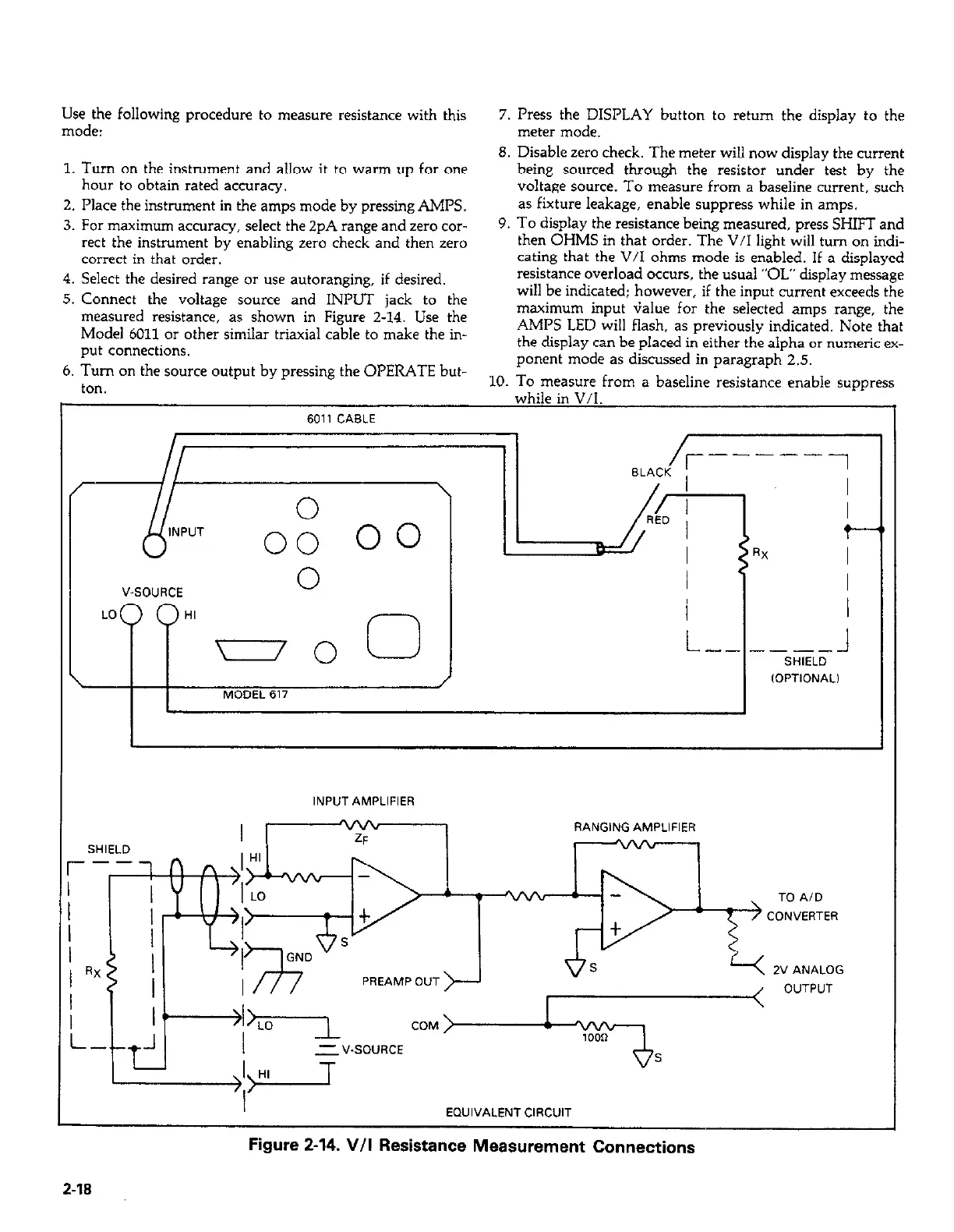
5. Connect the voltage source and INPUT jack to the
measured resistance, as shown in Figure 2-14. Use the
Model 6011 or other similar triaxial cable to make the in-
put connections.
6. Turn on the source output by pressing the OPERATE but-
ton.
7. Press the DISPLAY button to return the display to the
meter mode.
8. Disable zero check. The meter will now display the current
being sourced through the resistor under test by the
voltage sowce. To measure from a baseline current, such
as fixture leakage, enable suppress while in amps.
9. To display the resistance being measured, press SHIFT and
then OHMS in that order. The V/I light will turn on indi-
cating that the V/I ohms mode is enabled. If a displayed
resistance overload occurs, the usual “OL” display message
will be indicated; however, if the input current exceeds the
maximum input G&e for the selected amps range, the
AMPS LED will flash, as previously indicated. Note that
the display can be placed in either the alpha or numeric ex-
ponent mode as discussed in paragraph 2.5.
10. To measure from a baseline resistance enable suppress
while in V/T
V-SOURCE
0
LO HI
-0 0
I
I
L-- -SELDl
/
IOPTlONALl
MODEL 617
rgure z-14. v/I Hesistance Measurement Connections