2.10.4 Non-standard Coulombs Ranges
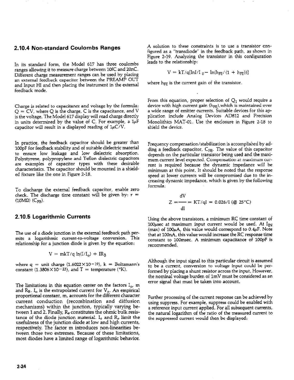
A solution to these constraints is to use a transistor con-
figured as a “transdiode” in the feedback path, as shown in
Figure Z-19. Analyzing the transistor in this configuration
In its standard form, the Model 617 has three coulombs
leads to the relationship:
ranges allowing it to measure charge between 1OfC and 20nC.
Different charge measurement ranges can be used by placing
V = kT/q[lnI/I o- In(h&(l + h&)1
an external feedback capacitor between the PREAMP OUT
and Inout HI and then olacing the instrument in the external
where hE is the current gain of the transistor.
feedback mode. . -
From this equation, proper selection of Q1 would require a
Charge is related to capacitance and voltage by the formula:
device with high current gain (h&,which is maintained over
Q = CV, where Q is the charge, C is the capacitance, and V
a wide range of emitter currents. Suitable devices for this ap-
is the voltage. The Model 617 display will read charge directly
plication include Analog Devices AD812 and Precision
in units determined by the value of C. For example, a IFF
Monolithics MAT-01. Use the enclosure in Figure 2-18 to
capacitor will result in a displayed reading of lpC/V. shield the device.
In practice, the feedback capacitor should be greater than
1COpF for feedback stability and of suitable dielectric material
to ensure low leakage and low dielectric absorption.
Polystyrene, polypropylene and Teflon dielectric capacitors
are examples of capacitor types with these desirable
characteristics. The capacitor should be mounted in a shield-
ed fixture like the one in Figure Z-18.
To discharge the external feedback capacitor, enable zero
check. The discharge time constant will be given by: T =
(lOM0) (Cm).
2.10.5 Logarithmic Currents
Frequency compensation/stabilization is accomplished by ad-
ding a feedback capacitor, Cm. The value of this capacitor
depends on the particular transistor being used and the maxi-
mum current level expected. Compensation at maximum cur-
rent is required because the dynamic impedance will be
minimum at this point. It should be noted that the response
speed at lower currents will be compromised due to the in-
creasing dynamic impedance, which is given by the following
formula:
dV
2 =-= KT/qI = 0.026/I (@ 25°C)
d1
Using the above transistors, a minimum RC time constant of
lC@sec at maximum input current would be used. At 11~
The use of a diode junction in the external feedback path per-
(m&) of lOOpA, this v&e would correspond to 0.4~F. No&
that at loOnA this value would increase the RC resoonse time
mits a logarithmic current-to-voltage conversion. This
relationship for a junction diode is given by the equation:
constant to 100msec. A minimum capacitance of 1OOpF is
recommended.
V = mkT/q h-@/I,) + IRB
where q = unit charge (1.6022X10⁻¹⁹). k = Boltzmann’s
constant (1.3806X10-U). and T = temperature (OK).
The limitations in this equation center on the factors I,, m
and RB, I, is the extrapolated current for V,. An empirical
proportional constant, m, accounts for the different character
current conduction (recombination and diffusion
mechanisms) within the junction, typically varying be-
tween 1 and 2. Finally, R, constitutes the ohmic bulk resis-
tance of the diode junction material. I0 and R, limit the
usefulness of the junction diode at low and high currents,
respectively. The factor m introduces non-linearities be-
tween those two extremes. Because of these limitations,
most diodes have a limited range of logarithmic behavior.
Although the input signal to this particular circuit is assumed
to be a current, conversion to voltage input could be per-
formed by placing a shunt resistor across the input. However,
the nominal voltage burden of 1mV must be considered as an
error signal that must be taken into account.
Further processing of the current response can be achieved by
using suppress. For example, suppress could be enabled with
a reference input current applied. For all subsequent currents,
the natural logarithm of the ratio of the measured current to
the suppressed current would then be displayed:
2-24