I
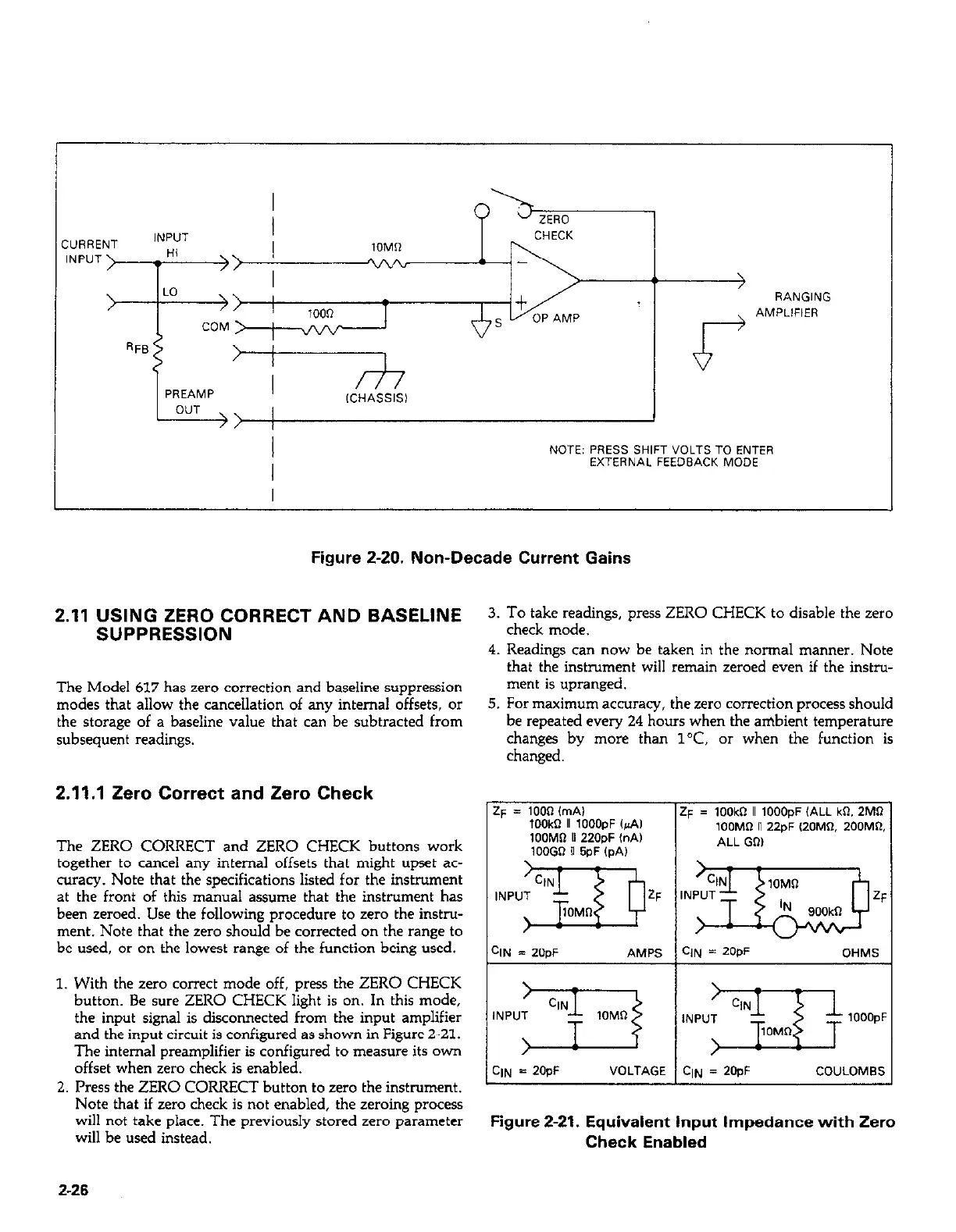
NOTE: PRESS SHIFT VOLTS TO ENTER
I
EXTERNAL FEEDBACK MODE
I
Figure Z-20. Non-Decade Current Gains
2.11 USING ZERO CORRECT AND BASELINE
3. To take readings, press ZERO CHECK to disable the zero
SUPPRESSION
check mode.
The Model 617 has zero correction and baseline suppression
modes that allow the cancellation of any internal offsets, or
the storage of a baseline value that can be subtracted from
subsequent readings.
4. Readings can now be taken in the normal manner. Note
that the instrument will remain zeroed even if the instru-
ment is upranged.
5. For maximum accuracy, the zero correction process should
be repeated every 24 hours when the ambient temperature
chants bv more than 1°C. or when the function is
2.11.1 Zero Correct and Zero Check
The ZERO CORRECT and ZERO CHECK buttons work
together to cancel any internal offsets that might upset ac-
curacy. Note that the specifications listed for the instrument
at the front of this manual assume that the instrument has
been zeroed. Use the following procedure to zero the instru-
ment. Note that the zero should be corrected on the range to
be used, or on the lowest range of the function being used.
changed. .
2~ = 1003 (mAI
lOOk II 1OOOpF Cd,
1OOMO II 22OpF InA)
lOOGO n 5PF IDA,
i+ = lOOk II lOOO,,F (ALL kn. 2MQ
IOOMR n 22pF (20MR. 200MR
ALL GO)
1. With the zero correct mode off, press the ZERO CHECK
button. Be sure ZERO CHECK light is on. In this mode,
the input signal is disconnected from the input amplifier
and the input circuit is coofigured as shown in Figure 2-21.
The internal preamplifier is configured to measure its own
offset when zero check is enabled.
2. Press the ZERO CORRECT button to zero the instrument.
Note that if zero check is not enabled, the zeroing process
will not take place. The previously stored zero parameter
will be used instead.
GIN = 2OpF AMPS GIN = 2W OHMS
I
GIN = 2OpF
VOLTAGE C,,, = 2OpF COULOMB:
Figure 2-21. Equivalent input Impedance with Zero
Check Enabled
2-26