r
I
MODEL 705
0
COMPLETE TRIGGER
OUTPUT
INPUT
00
MODEL 617
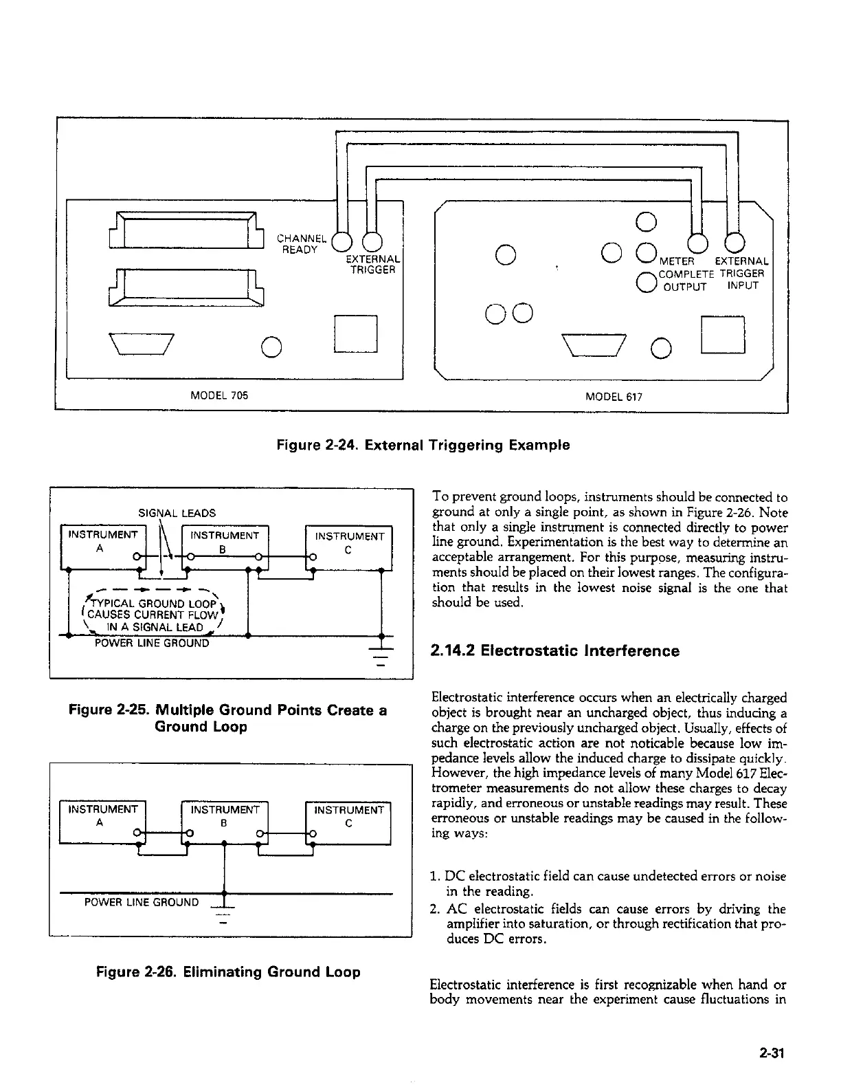
Figure 2-24. External Triggering Example
To prevent ground loops, instruments should be connected to
ground at only a single point, as shown in Figure Z-26. Note
INSTRUMENT
INSTRUMENT
s
T
I
------\
r;YPlCAL GROUND LOOP,
(CAUSES CURRENT FLOW
. IN A SIGNAL LEAD,/
POWER LINE GROUND
-
Figure 2-25. Multiple Ground Points Create a
Ground Loop
INSTRUMENT
INSTRUMENT
INSTRUMENT
POWER LINE GROUND
_
-
that only a single instrument is connected directly to power
line ground. Experimentation is the best way to determine an
acceptable arrangement. For this purpose, measuring instru-
ments should be placed on their lowest ranges. The configura-
tion that results in the lowest noise signal is the one that
should be used.
2.14.2 Electrostatic Interference
Electrostatic interference occurs when an electrically charged
object is brought near an uncharged object, thus inducing a
charge on the previously uncharged object. Usually, effects of
such electrostatic action are not noticable because low im-
pedance levels allow the induced charge to dissipate quickly.
However, the high impedance levels of many Model 617 Elec-
trometer measurements do not allow these charges to decay
rapidly, and erroneous or unstable readings may result. These
erroneous or unstable readings may be caused in the follow-
ing ways:
1. DC electrostatic field can cause undetected errors or noise
in the reading.
2. AC electrostatic fields can cause errors by driving the
amplifier into saturation, or through rectification that pro-
duces DC errors.
Figure 2-26. Eliminating Ground Loop
Electrostatic interference is first recognizable when hand or
body movements near the experiment cause fluctuations in
2-31