Front Panel Operation
2-62
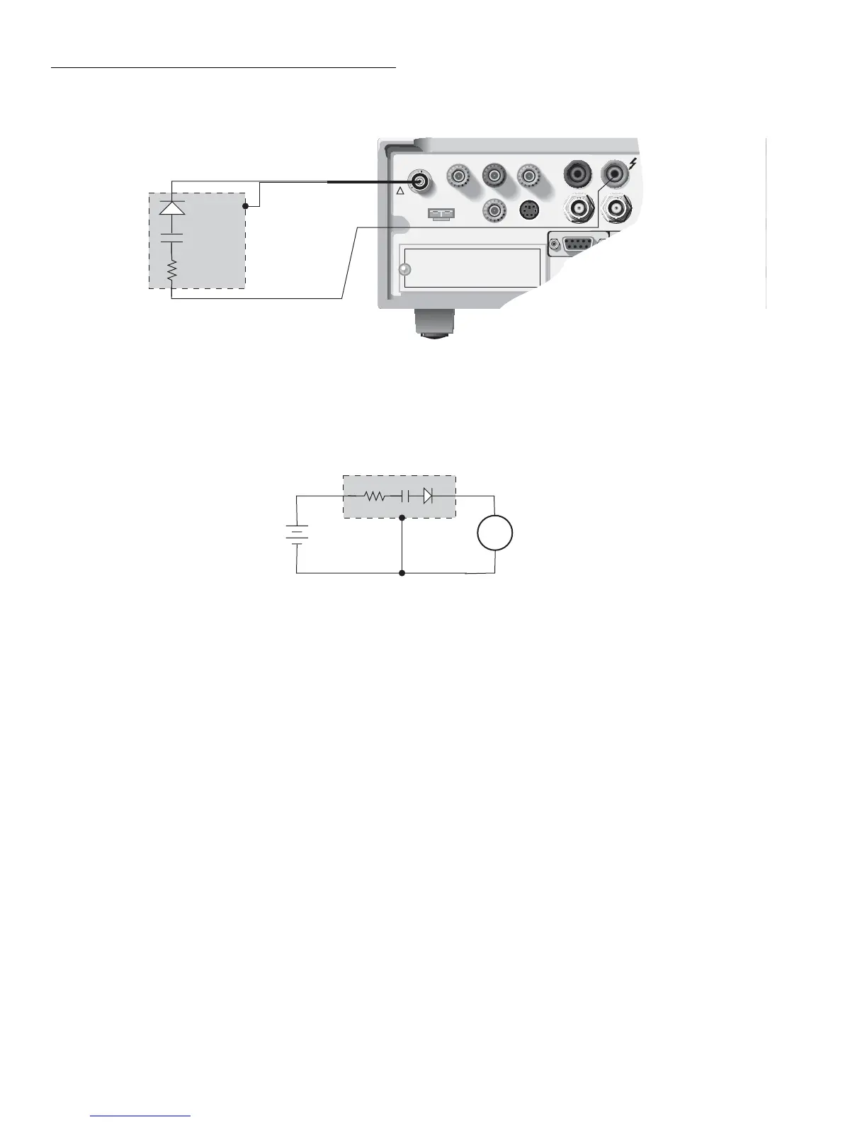
Cable insulation resistance test
This test is used to measure the insulation resistance of a ca-
ble. Figure 2-50 shows the connections for this test. The re-
sistance of the insulator between the shield and the inner
conductor is being measured. The cable sample should be
kept as short as possible to minimize input capacitance to the
ammeter.
For this test a fixed voltage (BIAS V) is applied across the in-
sulator for a specified time to allow the charging effects of
cable capacitance to stabilize. The resistance is then mea-
sured and stored in the buffer. This test is selected and con-
figured from the CONFIGURE SEQUENCE menu (DEV-
CHAR; CABLE). See paragraph 2.14.2 for details.
Resistor voltage coefficient test
High valued resistors often have a change in resistance with
applied voltage. This change in resistance is characterized as
6517A
HI
Diode
6517A
V-Source
A
+
-
6517A
Ammeter
CAUTION:FOR CONTINUED PROTECTION AGAINST FIRE HAZARD,REPLACE FUSE WITH SAME TYPE AND RATING.
CAUTION:FOR CONTINUED PROTECTION AGAINST FIRE HAZARD,REPLACE FUSE WITH SAME TYPE AND RATING.
WARNING:NO INTERNAL OPERATOR SERVICABLE PARTS,SERVICE BY QUALIFIED PERSONNEL ONLY.
WARNING:NO INTERNAL OPERATOR SERVICABLE PARTS,SERVICE BY QUALIFIED PERSONNEL ONLY.
7078-TRX Cable
INPUT
250V PEAK
COMMON
TRIGGER
LINK
IN OUT
!
LINE RATING
90-134VAC
180-250VAC
50, 60, 400HZ
55VA MAX
LINE FUSE
SLOWBLOW
1/2A, 250V
IEEE-488
(CHANGE IEEE ADDRESS
WITH FRONT PANEL MENU)
PREAMP OUT
250V PEAK
V SOURCE
LO HI
Note: Ammeter LO internally
connected to V-Source
LO (See Paragraph 2.9.1).
A) Connections
HI
LO
HI
LO
B) Equivalent Circuit
Capacitor
DUT
Resistor
LO
Figure 2-49
Connections; capacitor leakage current test
the voltage coefficient. Voltage coefficient is defined as the
percent change in resistance per unit change in applied volt-
age:
This test makes two resistance measurements at two different
voltage levels, and calculates the voltage coefficient. The test
circuit is shown in Figure 2-51. The resistor should be placed
in a shielded test fixture that is designed to minimize leakage
resistance, such as the Model 8002A test fixture. If using the
Model 8002A, refer to Figure 2-32 for connection informa-
tion. If using a different test fixture, refer to Figure 2-31 for
basic connection information.
For this test, the first specified voltage (SOURCE V1) is ap-
plied to the resistor and, after the specified delay (DELAY 1),
a resistance measurement is made. The second voltage
Voltage Coefficient
R1 R2–
R1
--------------------
1
V2 V1–
--------------------
×=