S301581
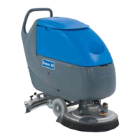
Electronic board for Razor™ 20
Supplier Ref. Ref. Rev. Spec.
7CFBA600 Till S/N 072115094
7CFBA606 current version
Electronic board for Razor™ 20T
Supplier Ref. Ref. Rev. Spec.
7CFBA700 Till S/N 072014255
7CFBA706 current version
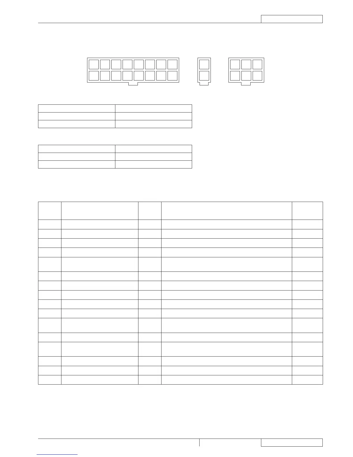
CONNECTORS (on B side card)
J1: MOLEX MINIFIT type 16 ways vertical
PIN Description
Electronic
board
in/out
V ref. Connected to
1 Electronic board power supply +
BOARD
24V always, with connected batteries BAT
2 Ignition key circuit power supply
IN/OUT
24V always, with connected batteries K1
3 Auxiliary signal power supply OUT 24V always, with connected batteries SW1 SW2
4 Hour counter power supply OUT 0V with Vacuum function activated HM
5
Drive system electronic board
enabling
OUT 24V with key on “I” EB2.J1.15
6 Return from ignition key IN 24V with key on “I” K1
7 - - - -
8 Electronic board power supply - IN 0V always, with connected batteries BAT
9 Brush fuse voltage drop reading + IN 0 ÷ 50mV nearly proportional to the current in brush motors F1
10 Brush fuse voltage drop reading - IN 0V always, with connected batteries F1
11
Brush electromagnetic switch power
supply -
OUT 0V with brush function activated ES1
12 Vacuum system relay power supply - OUT 0V with Vacuum function activated ES2
13
Electromagnetic switch/relay power
supply +
OUT 24V with key on “I” ES1-ES2
14 Brush motor braking circuit IN 24V with brush function deactivated ES1.NC
15 Drive system/brush enabling (panel) IN 24V with pressed paddle SW1
16 -
 Loading...