2-2 Installation and Connection to Sensor Amplifiers
2-5
2
Connection and Configuration
- EtherNet/IP Compatible Network Unit DL-EP1 User’s Manual (GT2) -
3
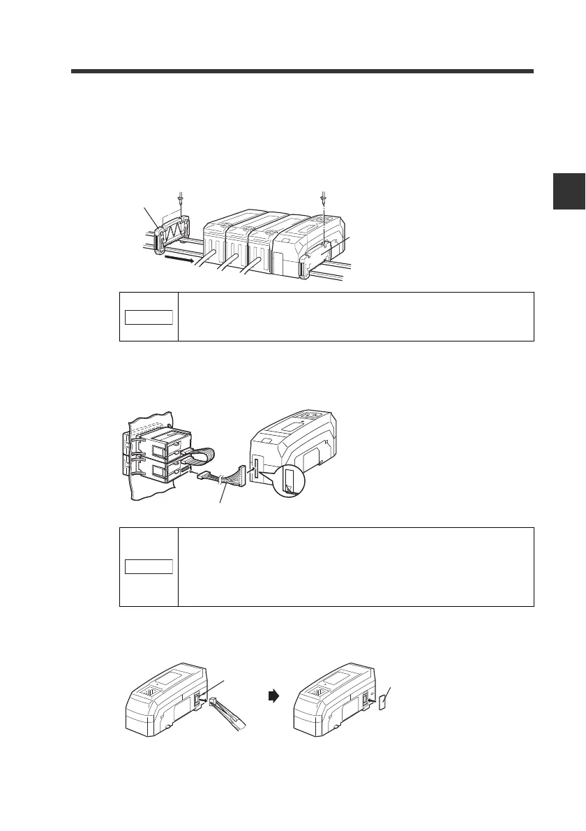
Mount the supplied end units (OP-26751: a set of two pieces) on the outer
ends of the amplifier and the EtherNet/IP Compatible Network Unit DL-
EP1. Then, fix the end units with the screws on the top of each end unit (2
points x 2 units). (Tightening torque : 0.6 N•m or less)
Mount the end units in the same way as the EtherNet/IP Compatible Network
Unit DL-EP1.
z Connecting to sensor amplifiers of panel mount type
1
Connect the sensor amplifier and the EtherNet/IP Compatible Network
Unit DL-EP1, with the optional expansion cable (OP-35361).
2
Remove the sensor amplifier connector (for DIN rail mount type) from the
EtherNet/IP Compatible Network Unit DL-EP1 using pliers. Then, attach
the expansion connector sticker supplied with the DL-EP1.
Press the EtherNet/IP Compatible Network Unit DL-EP1, into
full engagement with the sensor amplifier. Energizing the DL-
EP1 when not inserted fully may damage the DE-EP1.
• Turn off the power supply and connect the expansion cable
securely. Energizing the DL-EP1 when not inserted fully
may damage the DL-EP1.
• Attaching or detaching the cable when the power supply is
on may damage the DL-EP1.
End unit
End unit
Peel off the protective sticker.
Expansion cable (Cable length: 300 mm)
Sensor amplifier connector
(for DIN rail mounting type)
Expansion
connector sticker
 Loading...