3-3 Cyclic communication
3-17
3
Communicating with the GT2 Series
- EtherNet/IP Compatible Network Unit DL-EP1 User’s Manual (GT2) -
The following describes how the scanner cyclically communicates with the DL-EP1
(cyclic communication).
"Reading an output from a sensor amplifier" (Page 3-17)
"Entering an external input to a sensor amplifier" (Page 3-18)
"Reading comparator values (P.V. values) from sensor amplifiers" (Page 3-19)
For the message communication method, refer to "Message communication"
(Page 3-4).
Reading an output from a sensor amplifier
Available outputs: HIGH, LOW, GO, HH, and LL
Device assignments: "Monitor Data (84 Words (168 Bytes)) Assembly Instance
(Instance ID): 64H" (Page 3-9)
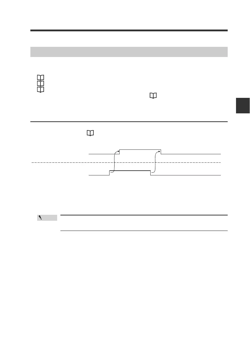
This example shows how to read the HIGH output from the sensor amplifier ID01.
(1)The output from the sensor amplifier entered into the IN area via cyclic
communication.
To use the HH output and LL output, set "Special Output Setting" of the
sensor amplifier to "5-Output".
Communication Methods
PLC
Output of sensor amplifier
IN area [18] Bit0
Sensor amplifier
(1)
Output
HIGH output of ID 01
1
0
ON
OFF