- EtherNet/IP Compatible Network Unit DL-EP1 User’s Manual (GT2) -
3-3 Cyclic communication
3-8
3
Communicating with the GT2 Series
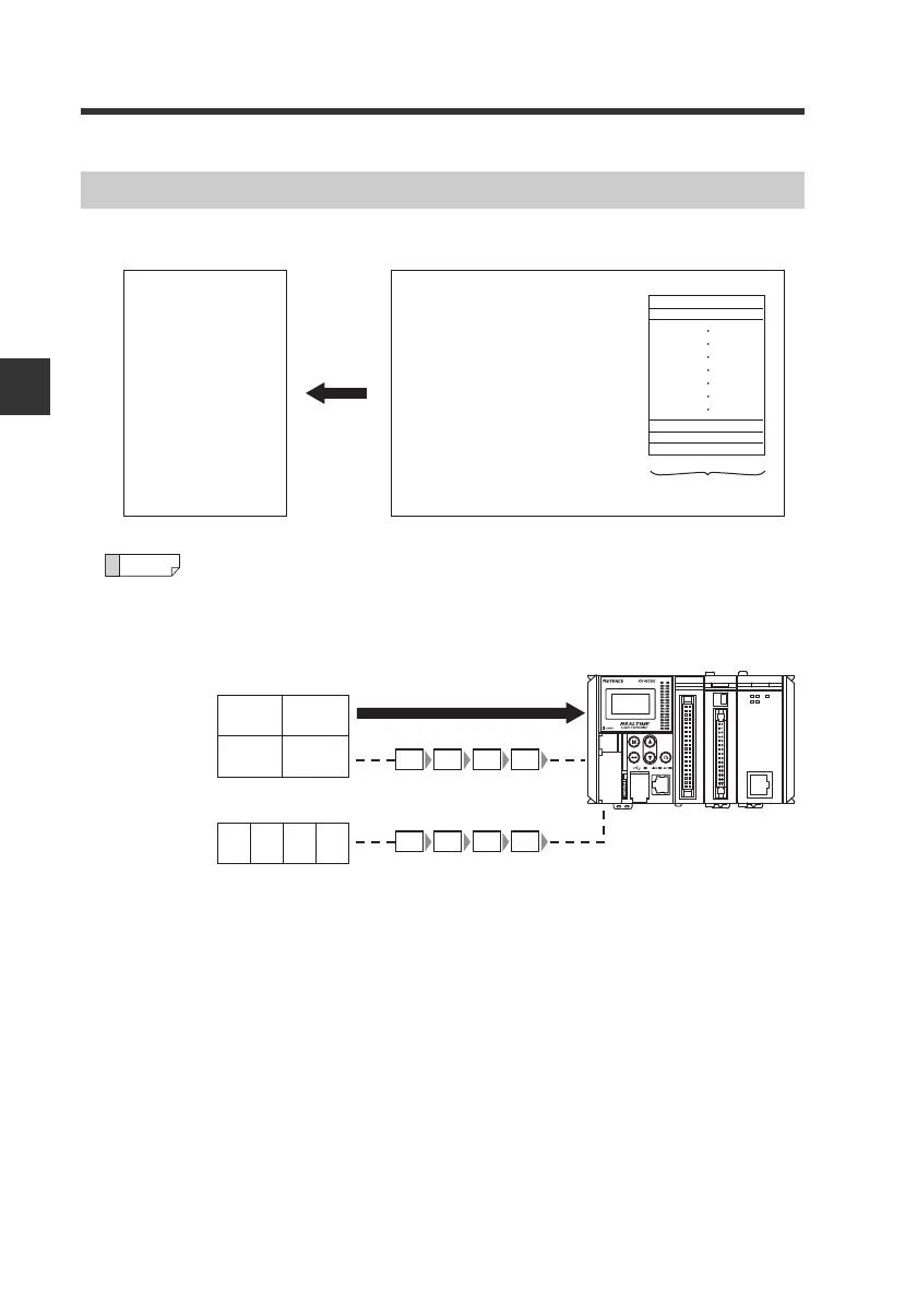
The data from the DL-EP1 is assigned to the EtherNet/IP scanner's IN area.
The data such as 16-bit data extending over multiple bytes is stored into
an area which starts with an even address in order from the lowest-order
byte.
Example)
Assignment to IN Area (DL-EP1 to Scanner)
DL-EP1 data
Scanner IN area
Address 0
Address 1
Address 167
Monitor Data
(Assembly Instance: 100)
1-byte (8-bit) data
16-bit data
Address 40 to 41
16-bit data
Address 42 to 43
12H 34H
56H 78H
High-order byte Low-order byte
High-order byte Low-order byte
56H
43
78H
42
12H
41
34H
40
32-bit data
Address 48 to 51
12H
51
34H
50
56H
49
78H
48
12H 34H 56H 78H