- EtherNet/IP Compatible Network Unit DL-EP1 User’s Manual (GT2) -
2-2 Installation and Connection to Sensor Amplifiers
2-6
2
Connection and Configuration
Several sensor amplifiers can be connected to the DL-EP1. ID numbers for data
identification are assigned to each sensor amplifier.
The method for assigning ID numbers is as follows:
• ID numbers are assigned in order, starting from the sensor amplifier that is the
main unit. (Optional numbers cannot be assigned.)
• 0 is assigned as the ID number of the DL-EP1.
• You cannot change the ID numbers assigned to the sensor amplifiers.
• In this manual, ID number 00 to ID number 15 are denoted as ID00 to
ID15, respectively.
Also for cyclic communication, output, current value, and external input are assigned
one by one per ID number.
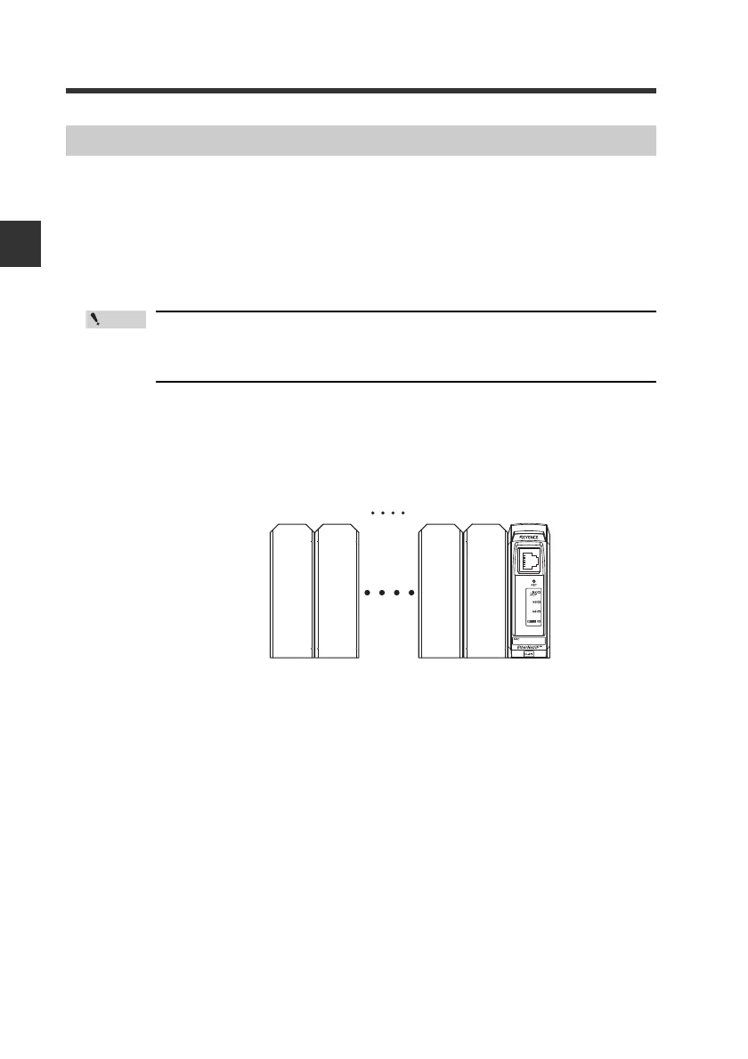
For DIN rail mount type
Assigning ID Numbers
ID number 01
Main
unit
Expansion
unit
Expansion
unit
Expansion
unit
02 14 15 00