20
Before starting the measurements, connect the cables between the B1505A and the
N1259A depending on your B1505A configurations. These connections are used for
all the measurement examples, and there is no need for changing this configuration
later.
This configuration is used when only one HCSMU is installed in the B1505A.
Connect the cables between the B1505A and the N1259A as shown in figure 2-6 by
following the step number 1 to 6.
The breakdown of each steps with cable figures and the connector locations are
shown in figure 2-7.
Step number 1:
Using a 16493J Interlock Cable, connect the Interlock on the B1505A and the
Interlock on the N1259A
Tips:
For connecting the interlock cable, hold the black plastic part and then turn
the connector by pressing toward the interlock connector in the instrument
side as shown in figure 2-8.
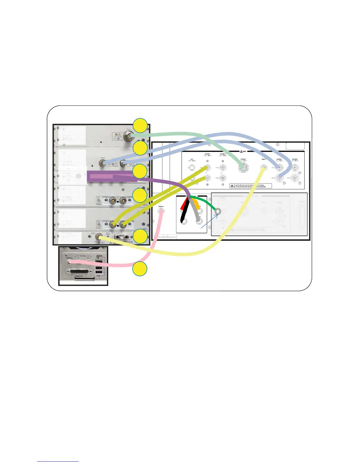
2-4. Cable Connection between the B1505A and the N1259A Test Fixture
2-4-1. 2 x HPSMU and 1 x HCSMU configuration
Back side of the B1505A
Back side of the N1259A
1
2
3
6
5
4
B1513A
HVSMU
B1512A
HCSMU
B1510A
HPSMU
B1510A
HPSMU
B1520A
MFCMU
GNDU
Leave it open
CoaxTriax
Coax
Triax
Figure 2-6. Connections for 2x HPSMU and 1x HCSMU Configuration.