9
Agilent N1259A Power Device Fixture shown in fig-
ure 1-2 is used for measuring packaged power de-
vices, It can basically covers the B1505A`s maximum
output range; 40 A and 3 kV.
We use N1259A option 020 High Voltage Bias-Tee
and option 022 100 kΩ resistor (optional) shown in
figure 1-3.
The module selector option 300 is handled in the
appendix section.
We do not use options 033 1 kΩ resistor in BJT ap-
plication.
Option 020 High Voltage Bias-Tee is required if you
perform a CV measurement with more than 25 V DC
bias, and it expands the DC bias range up to 3 kV
with HVSMU. You can perform the CV measurement
without Option 020 if the requirement of maximum
bias voltage is less than 25 V which can be output
from MFCMU-self.
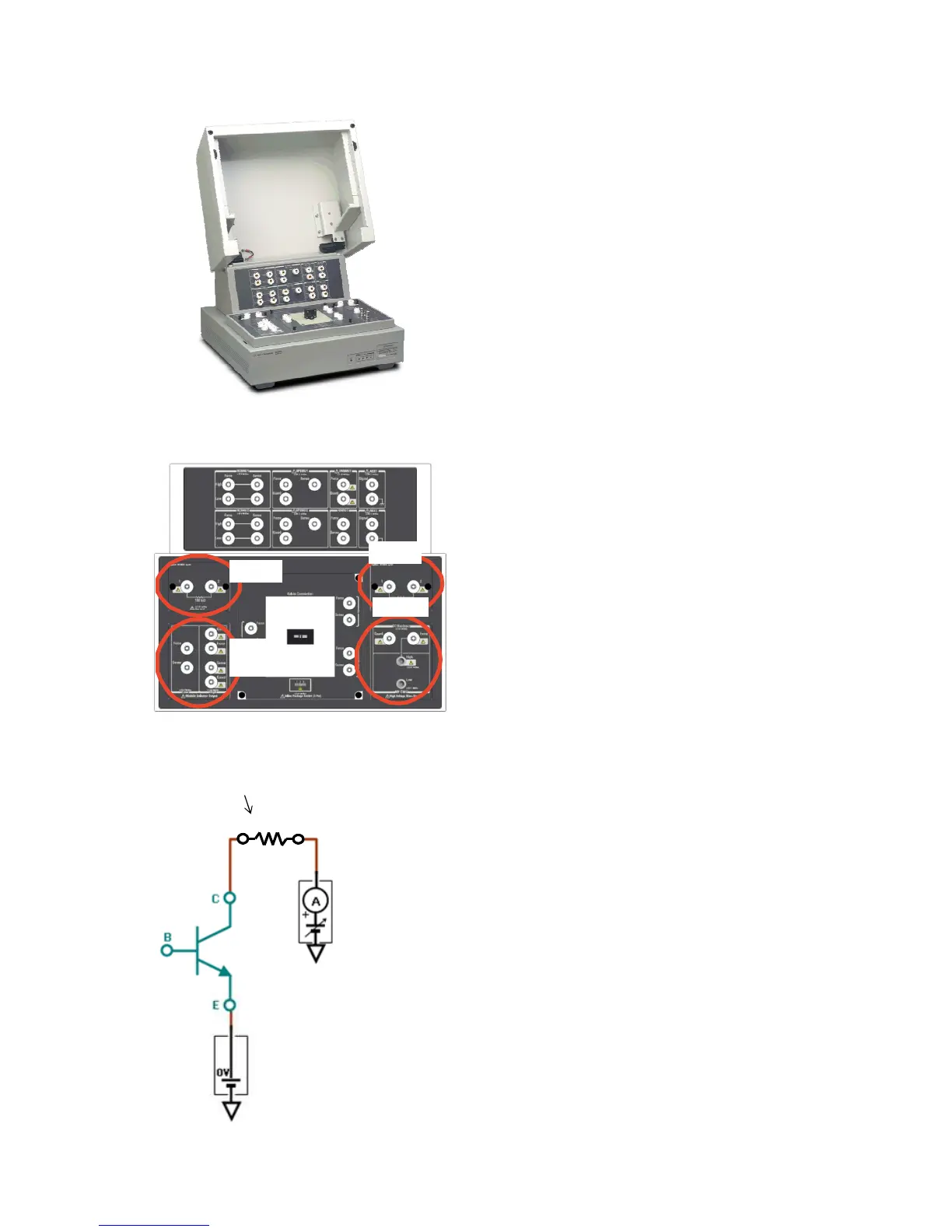
Option 022 100 kΩ resistor is basically used by in-
serting a 100 kΩ resistor in series between the
HVSMU and the collector of the power BJT as
shown in Figure 1-4.
Figures 1-2. Agilent N1259A Test Fixture
Opt 033
Opt 300
(Output)
Opt 020
Opt 022
Figure 1-3. N1259A Opt 020, 022, 033 and 300
1 00kΩ
ΩΩ
Ω
R
GNDU
HVSMU
Protective resistor
Figure 1-4. Option 022 Series R inserted between the collector and the collector HVSMU.
1-2. Agilent N1259A Power Device Fixture