16
HCSMU
MFCMU
HVSMU
HPSMU
HCSMU
HCSMU
HPSMU
MFCMU
HVSMU
HPSMU
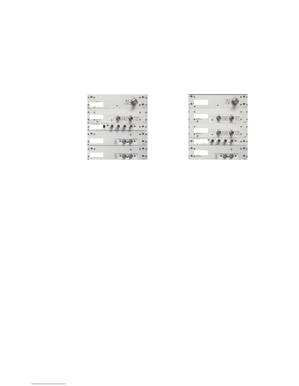
(B) Two HCSMU and one
HPSMU configuration.
(A) Two HPSMU and one
HCSMU configuration.
We use the following two B1505A configurations in the measurement example,
Both configurations are used for 20 A collector output. The difference is the maxi-
mum base current is limited to 1 A in the configuration of figure 2-1(A) that uses
two HPSMUs and one HCSMU, but the other configuration that uses one HPSMU
and two HCSMUs (figure 2-1(B)) can drive more than 1A by using one of HCSMUs.
You can use the same example files by just replacing the corresponding SMU
names.
Agilent B1505A Power Device Analyzer/Curve Tracer
2 x HPSMU and 1 x HCSMU configuration:
●
1 X HVSMU (B1513A) High Voltage SMU
●
1 X HCSMU (B1512A) High Current SMU
●
2 X HPSMU (B1510A) High Power SMU (Note: only one HPSMU is used in
the example)
●
1 X MFCMU (B1520A) Multi-Frequency CMU
1 x HPSMU and 2 x HCSMU configuration:
●
1 X HVSMU (B1513A) High Voltage SMU
●
2 X HCSMU (B1512A) High Current SMU
●
1 X HPSMU (B1510A) High Power SMU
●
1 X MFCMU (B1520A) Multi-Frequency CMU
2-2. Instruments and Accessories used in the measurement examples
Figure 2-1. B1505A configuration used in the example.