Keysight EXG and MXG X-Series Signal Generators User’s Guide 123
Optimizing Performance for All Models
Using Unleveled Operating Modes
— Fixed – Reference level is 0.5 Vrms.
This reference functions with internal, external IQ and bursted signals. This is the instrument’s
default setting.
— RMS – User provided reference level 0–1.414 Vrms placed in the Waveform Header. Refer to
“Saving a Waveform’s Settings & Parameters” on page 163.
This reference functions with internal IQ and bursted signals.
— Manual – User provided reference level 0–1.414 Vrms.
This reference functions with internal, external IQ and bursted signals.
— Modulated – Uses the I/Q modulation signal as the reference level.
This reference functions with internal or external IQ. It is not functional with bursted signals or a
signal with varying Vrms.
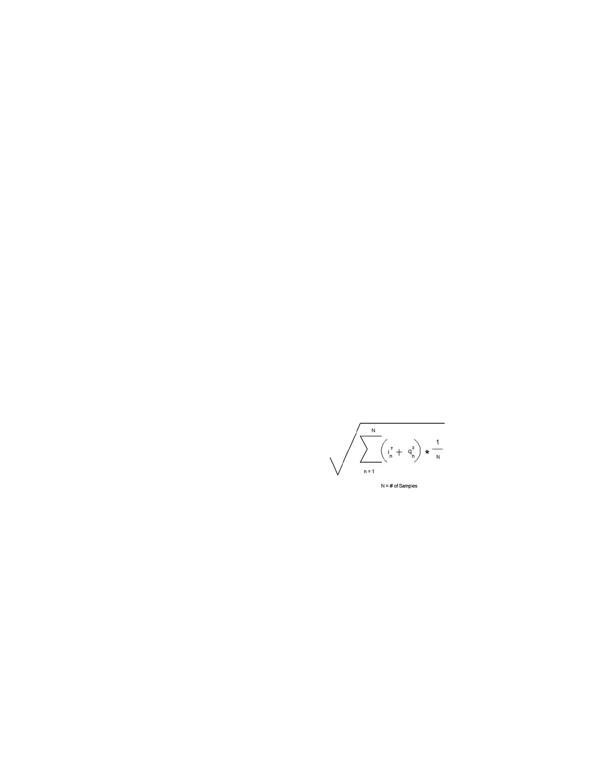
Figure 5-24 Calculating the Output Power Error for a Single Waveform Sample Point
Figure 5-25 Calculating the RMS Voltage of the Waveform
The RMS and MANUAL references are the most powerful selections. The user provides the reference
level. The IQ signal can be bursted (radar) or have different RMS levels (Wireless Signals). Once the
RMS/MANUAL reference level is set, the power search runs independent of the current Vrms value
of the waveform.
The RMS and MANUAL references, with a reference level of 1.0 Vrms are equivalent to a calculated
rms value of 1 and can be measured using SINE_TEST_WFM.
20 10 V1()V2()⁄()log×=
Where:
V1 is the actual waveform RMS voltage
V2 is the entered RMS voltage
The Output Power Error
Note: If the RMS voltage value entered is lower than the actual RMS voltage, the output power will be higher than desired. If the RMS
voltage value entered is higher than the actual RMS voltage, the output power will be lower than desired.
The signal generator can calculate the RMS value automatically.if more
than two contiguous IQ data points are zero, the signal generator
calculation ignores those zero points. Also, because the RMS calculation,
that is done by the signal generator, is slow and may not be appropriate for
your application, it is recommended that the user calculate and enter in
their measured RMS value for the waveform file.
RMS value for the waveform =
SCPI Commands:
[:SOURce]:RADio:ARB:HEADER:RMS <"file_name">,<val>|UNSPecified
[:SOURce]:RADio:ARB:HEADER:RMS? <"file_name">
For a programming example of determining the RMS voltage of a waveform, refer to the Programming Guide and to the Documentation
CD that came with this instrument.