428 Keysight EXG and MXG X-Series Signal Generators User’s Guide
Using the N5102A Digital Signal Interface Module for N5172B/82B with Option 003/004 and
653/655/656/657
Clock Timing
Clock Timing for Serial Data
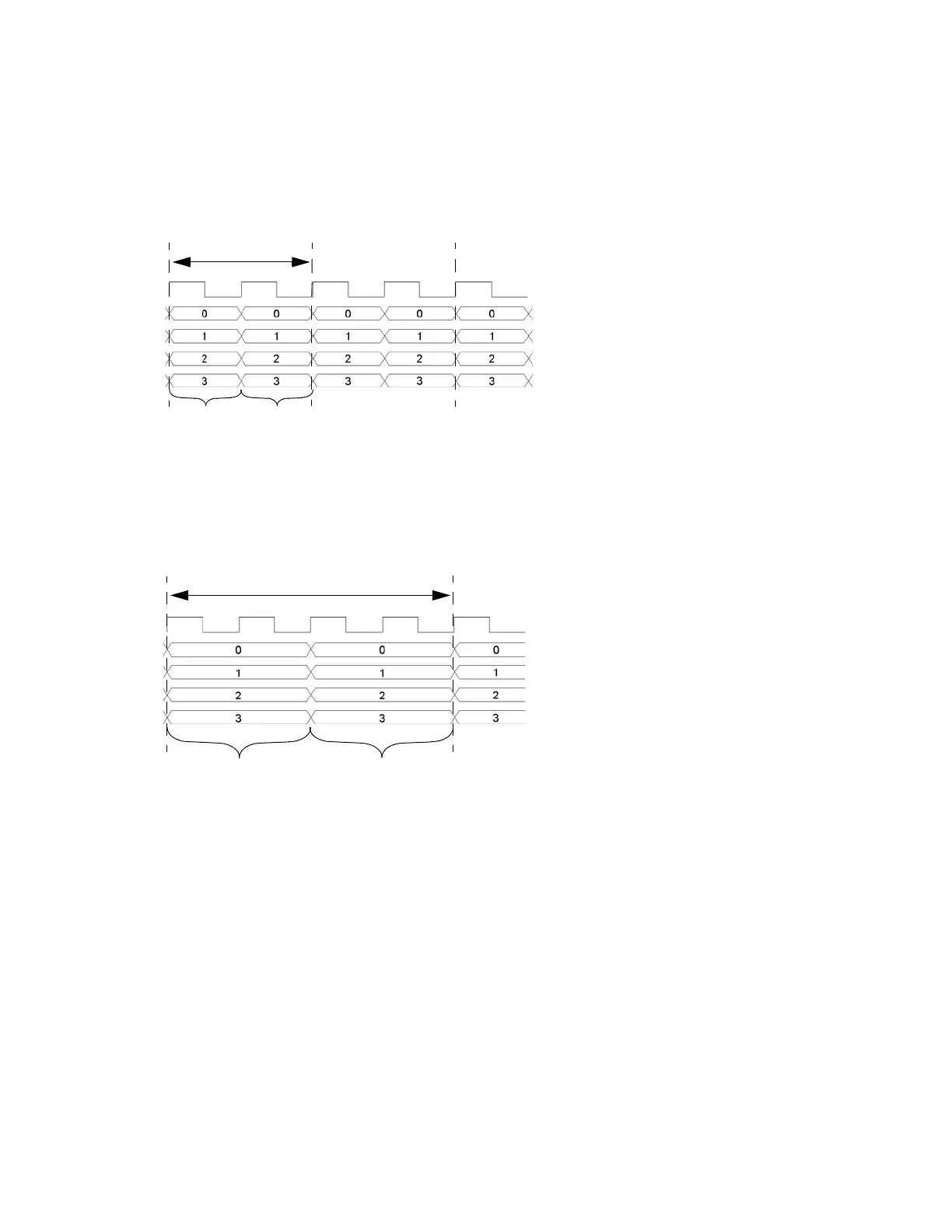
Figure 17-6 shows the clock timing for a serial port configuration. Notice that the serial
transmission includes frame pulses that mark the beginning of each sample where the clock
delineates the beginning of each bit. For serial transmission, the clock and the bit rates are the
same, but the sample rate varies depending on the number of bits per word that are entered using
the Word Size softkey. The number of bits per word is the same as the number of bits per sample.
1 Sample Period
4 Clocks Per Sample
4 Clocks
The I sample is transmitted for the first two clock periods and the Q sample is transmitted during the second two
Clock
Q sample
4 bits per word
I sample
4 bits per word
clock periods; the sample rate is decreased by a factor of four.
1 Sample Period
2 Clocks Per Sample
2 Clocks
The I sample is transmitted for one clock period and the Q sample is transmitted during the second
Clock
Q sample
4 bits per word
I sample
4 bits per word
clock period; the sample rate decreases by a factor of two.