406 Keysight EXG and MXG X-Series Signal Generators User’s Guide
Using BERT for N5172B/82B with Option UN7
Bit Error Rate Test
Gate Delay Function in the Clock Mode
To use this function, the clock must be set to continuous mode.
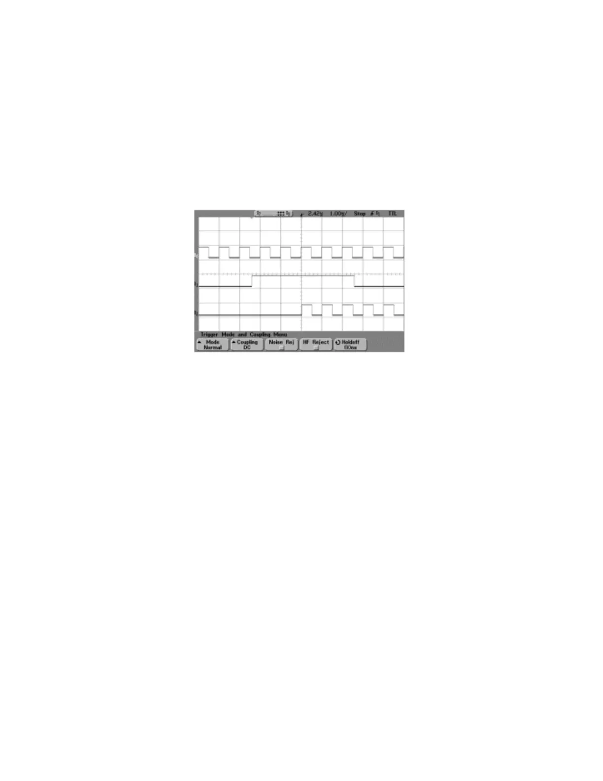
In this example, the clock is used to delay the gate function. The clock of the internal error detector
was gated by the gate signal which is delayed by two clocks. Figure 16-6 shows that CH0 and CH1
are the input of the clock and data from the rear panel input connectors of UN7. CH2 is the gated
clock through the AUX I/O connector.
Figure 16-6
CH0: BER CLK IN (rear panel BNC connector labeled BB TRIG 1)
CH1: BER GATE IN (rear panel BNC connector labeled BB TRIG 2)
CH2: BER TEST OUT (pin 17 of AUX I/O connector)