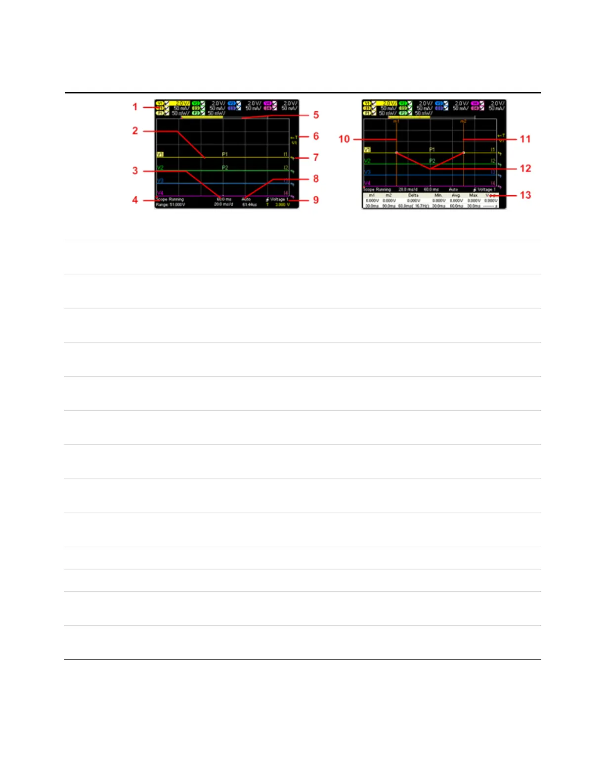
Scope View
Press Scope
View
This key
toggles
between
standard and
marker views.
Standard View
Marker View
1. Trace
Controls
Identifies the voltage or current trace that will be displayed. Dashes (----) indicate that the specified trace is turned off. Select
the traceand press Enter to turn iton or off.
2. Output
Traces
V1, V2, V3, and V4 indicatevoltage traces. I1, I2, I3, and I4 indicate current traces. P1 and P2 indicate power traces. Press
Trigger Level knob to autoscale all traces .
3. Horizontal
Time-base
Identifies the horizontal time-base settings. These can be adjusted using the front panel Horizontal Time/Div and Offset
knobs.
4. Scope
Status
Indicates whether the scope is idle, running, or waiting for a trigger.
5. Data Bar The highlighted area shows how much of the entire measurement is actually shown on the display. Use the Horizontal
Time/Div knob and Offsetknob to adjust the display
6. Trigger
Level
Identifies the trigger level through which the waveform must pass before the scope will trigger. This can be adjusted using
the Trigger Level knob.
7. Ground Identifies the ground reference level for the trace. This can be adjusted using the Vertical Offsetknob. The initial vertical offset
of each trace is setto a different level to prevent the traces from overlapping.
8. Trigger
Mode
Identifies the trigger mode setting. This can be selected by pressing the Properties key.
9. Trigger
Source
Identifies the trigger source and trigger level. Voltage 1 indicates a voltage level on output 1 is the trigger source (see #6).
10. M1 Marker Measurement Marker 1 enabled. Adjust using Marker 1 knob. Press knob to reset.
11. M2 Marker Measurement Marker 2 enabled. Adjust using Marker 1 knob. Press knob to reset.
12. Intersect
Point
Shows where the measurement markers intersectthe waveform.
13. Meas-
urements
Shows the calculations of the waveform data between Marker 1 and Marker 2.
1 Quick Reference
20 Keysight N6705C Operating and Service Guide