Disassembly/Assembly Procedures and Parts List 3
Keysight 3458A Assembly-Level Repair Manual 83
Installation procedure
1 Line up the A/D Converter and Inguard Logic board with the connector in the
inguard chassis. Then plug the board all the way into the connector.
2 Place the A/D Converter and Inguard Logic shield on the board. Then use the
#TX10 Torx driver to install the three screws on the shield.
3 Locate the gray 20-pin cable connected to the Inguard Power Supply
assembly. Line up the cable plug with the corresponding socket on the A/D
Converter and Inguard Logic assembly. Then plug the cable all the way in.
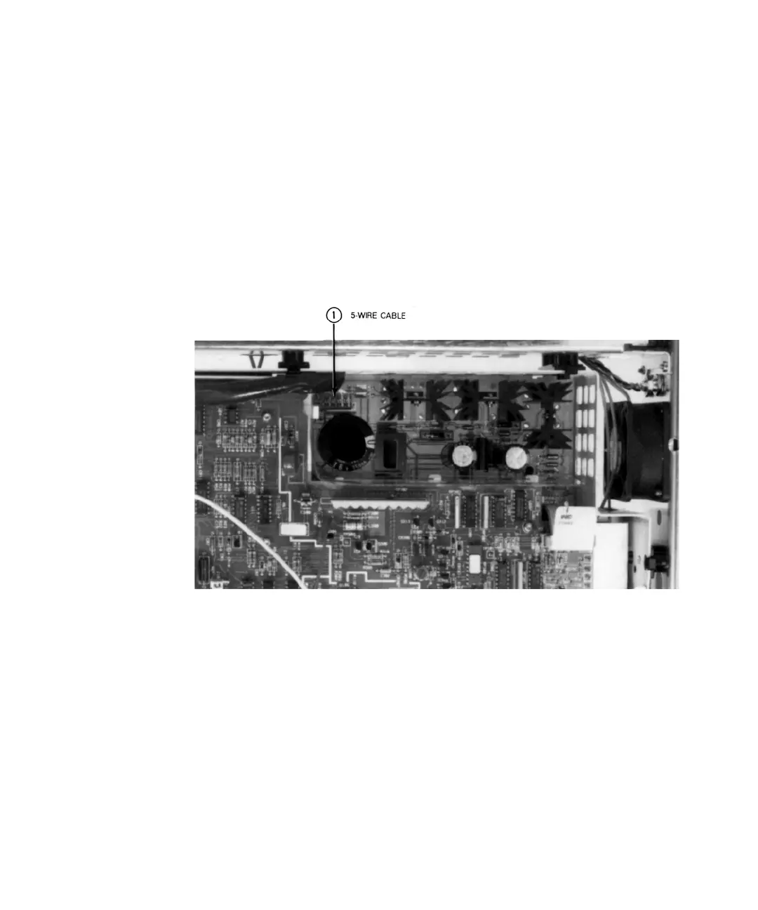
Figure 3-12 Remove/Install transformer cable on inguard power supply
4 Locate the gray 20-pin cable connected to the DC Circuitry assembly. Line up
the cable plug with the corresponding socket on the A/D Converter and
Inguard Logic assembly. Then plug the cable all the way in.
5 Plug in both sets of the blue and gray fiber optic cables into the corresponding
sockets on the A/D Converter and Inguard Logic assembly.
6 Use the Covers installation procedure in this section of the manual to install
the 3458A bottom cover and bottom shield.
NOTE
The label numbers in
Figure 3-11 and
Figure 3-12 show the
order assembly
removal. Use reverse
order for installation.