3 Disassembly/Assembly Procedures and Parts List
84 Keysight 3458A Assembly-Level Repair Manual
Inguard power supply assembly removal/installation procedures
The following procedures show how to remove and install the Inguard Power
Supply Printed Circuit Board Assembly.
Removal procedure
1 Use the Covers removal procedure in this section of the manual to remove the
3458A top/bottom covers and top/bottom shields.
2 Set the 3458A on your workbench with the top facing you.
3 Refer to Figure 3-12. Unplug the 5-wire cable from the Inguard Power Supply
assembly. This cable is connected to the power transformer.
4 Refer to Figure 3-13 for the rest of this procedure.
5 Set the 3458A on your workbench with the bottom facing you.
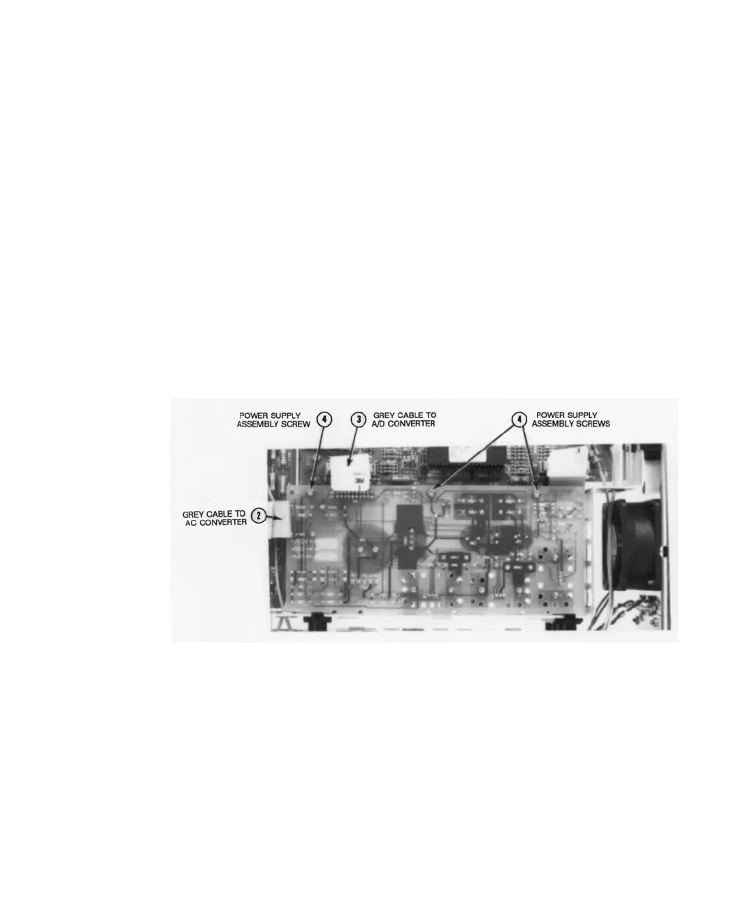
Figure 3-13 Inguard power supply assembly removal/installation
6 Locate the gray 20-pin cable that connects between the A/C Converter
assembly and Inguard Power Supply assembly. Unplug the cable at the power
supply assembly.
7 Locate the gray 20-pin cable that connects between the A/D Converter
assembly and Inguard Power Supply assembly. Unplug the cable at the power
supply assembly, and Inguard Logic assembly.