Keysight NFA Series Noise Figure Analyzers Service Guide 157
RF Section Troubleshooting (N8973B, 74B, 75B Analyzers)
Troubleshooting
6. Low Band Switch Control Logic Verification
Press Mode Preset on the analyzer. Press FREQ, 50 MHz, Span, 2MHz on the
analyzer. Connect the DVM positive lead to one of the In1A test points, and the
negative lead to the bottom of R46 (blue resistor near the bottom) on the Front
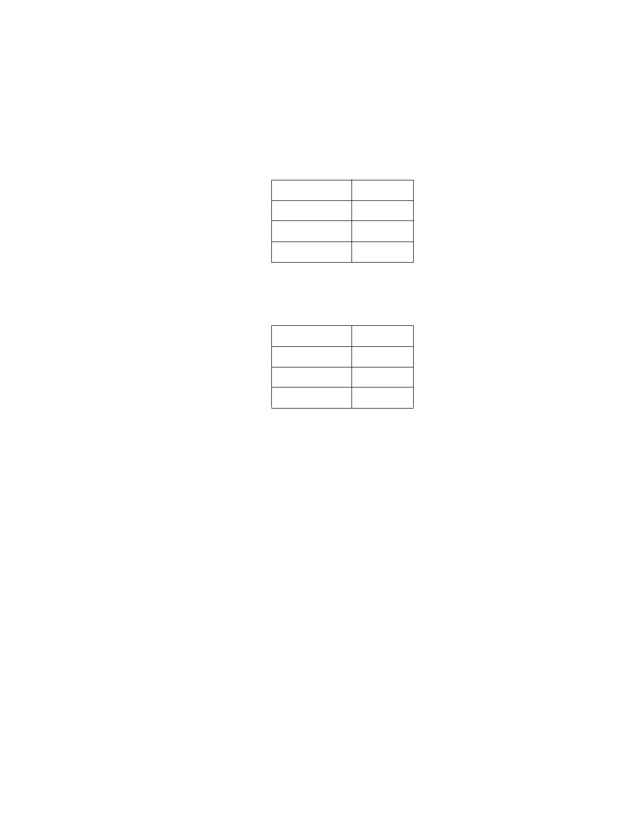
End Troubleshooting board. Verify the voltages in Table 4-5.
Press Center Frequency, 5 GHz on the analyzer. Verify the voltages in Table
4-6.
If the voltages are not correct, the most probable cause is the A15 Front End
Control Assembly.
Table 4-5
In1A −9.85
In2A −9.85
In1B +9.75
In2B +9.75
Table 4-6
In1A +9.72
In2A −9.84
In1B −9.84
In2B +9.72