158 Keysight NFA Series Noise Figure Analyzers Service Guide
RF Section Troubleshooting (N8973B, 74B, 75B Analyzers)
Troubleshooting
7. YTF Preselector Control Logic Verification
(All except N8973B)
Connect the mmcx end of the cable to A15J300, preselector tune output at the
upper left corner of A15 Front End Control Assembly.
Press Single/Cont on the analyzer until the analyzer is in single sweep. Verify
the voltages in Table 4-7 as the center frequency of the analyzer is changed.
Press Restart after each center frequency change.
If any of the preselector tune voltages do not match the levels shown in Table
4-7, the most probable causes are a misaligned YTF or the A15 Front End
Control Assembly. Perform the YTF characterization (press System,
Alignments, Advanced, Characterize Preselector).
To further test the YTF control current, select Amps on the DVM and place the
positive lead of the DVM on one of the YTF Coil Current P8 pins and the other
DVM lead to the other Coil Current pin.
In order to properly measure the preselector tune output from the A15
Front End Control Assembly, the following items are required:
— E9637A Banana plug to BNC (f) adapter
— E9632A BNC (M) to SMA (f)
— 8120-1460 Small coaxial cable SMA (m) to mmcx (m)
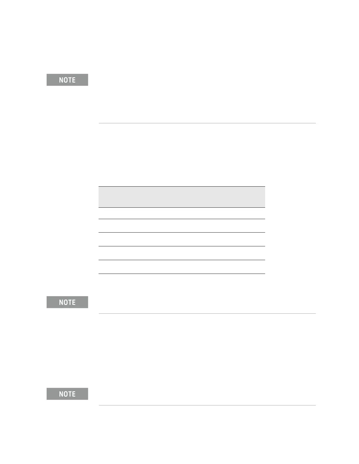
Table 4-7 YTF Tune Voltages
Center Frequency
(GHz)
~ Tune Voltage
(VDC)
Tolerance
(VDC)
5.0 1.6 ±0.5
10
a
3.228 ±1.0
15
a
4.85 ±1.0
20
a
6.5 ±1.0
26
a
8.45 ±1.0
a. N8975B/76B
Tolerances can be used as a guideline. The true test is whether or not the
analyzer will function and meet published specification.
In order to measure the control current correctly, press Restart on the
analyzer in between each measurement.