222 Keysight NFA Series Noise Figure Analyzers Service Guide
RF Section Troubleshooting (N8976B)
Troubleshooting
screen as explained in the quick check section. If the signal level is still
incorrect, suspect all assemblies, cables, switches and the A15 Reference
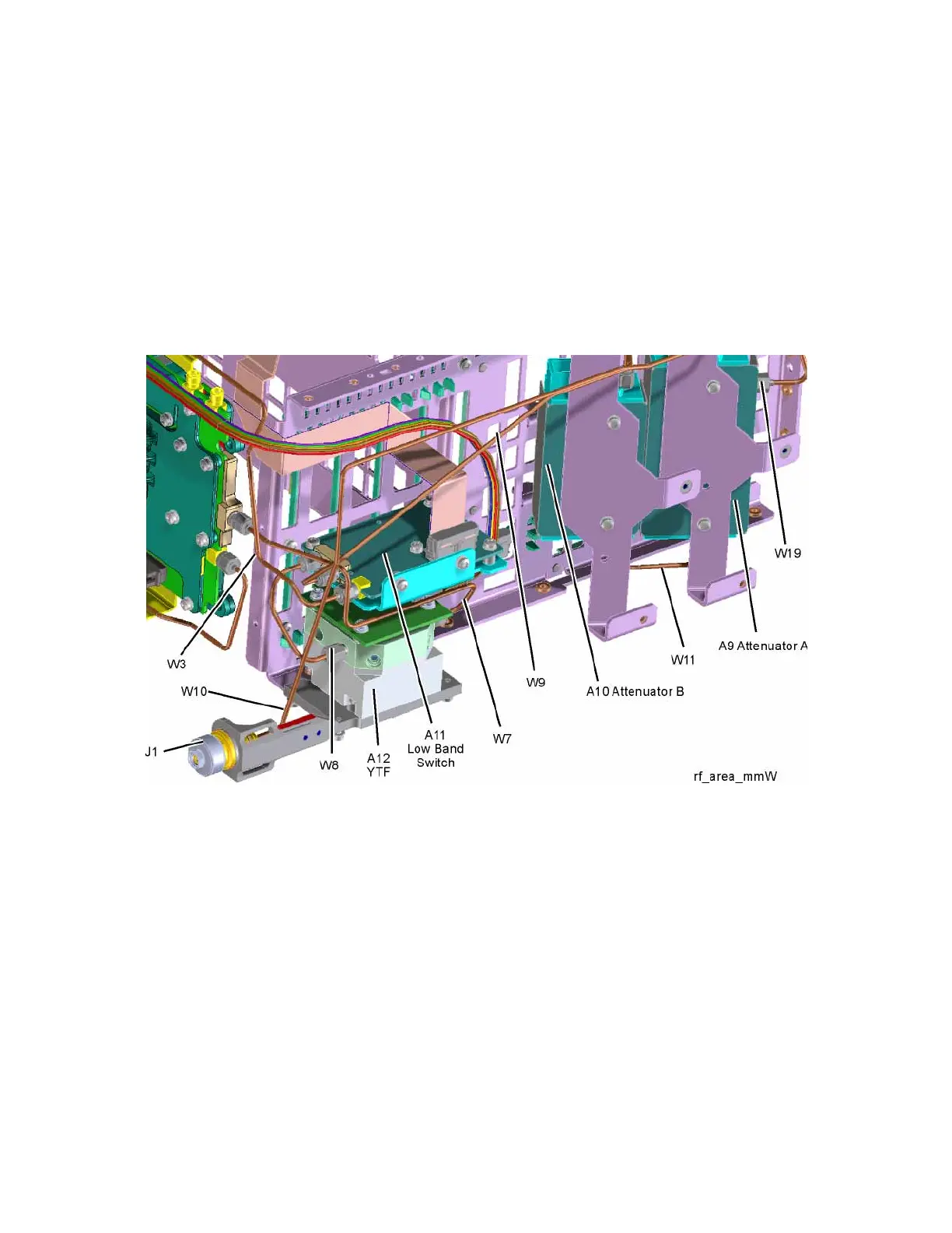
calibrator signal between the W7 cable and the input to the A9 Attenuator.
Remove A10 Input Attenuator B output cable and measure the output power.
Expected signal is 4.8 GHz −38 dBm. See Figure 5-11 for location of
attenuator. If the attenuator output signal is correct suspect the A11 Low Band
Switch. Also suspect the switching signals from the A15 Front End controller.
The control signals are explained in the Front End Control Troubleshooting
section.
Figure 5-11 RF Section
A9 Input Attenuator A and A10 Input Attenuator B Verification
Calibrator Switch Test
On the A16 Reference assembly, disconnect semi rigid cable W19 from
A16J701 and measure A16J701 with a spectrum analyzer. Expected signal is
4.8 GHz at −28 dBm ± 0.5 dB. If signal level is incorrect, suspect A16 Reference
Assembly.
To verify calibrator switch operation, connect external signal source set to
4.8 GHz and −25 dBm to the RF input connector of analyzer under test. Press
Input/Output, RF Calibrator, Off. If the signal level at the attenuator output is
now correct, suspect the A9 Attenuator cal switch or a faulty control signal
from the A15 Front End Controller assembly.