Installation
06-237619-001 4-5 April 2020
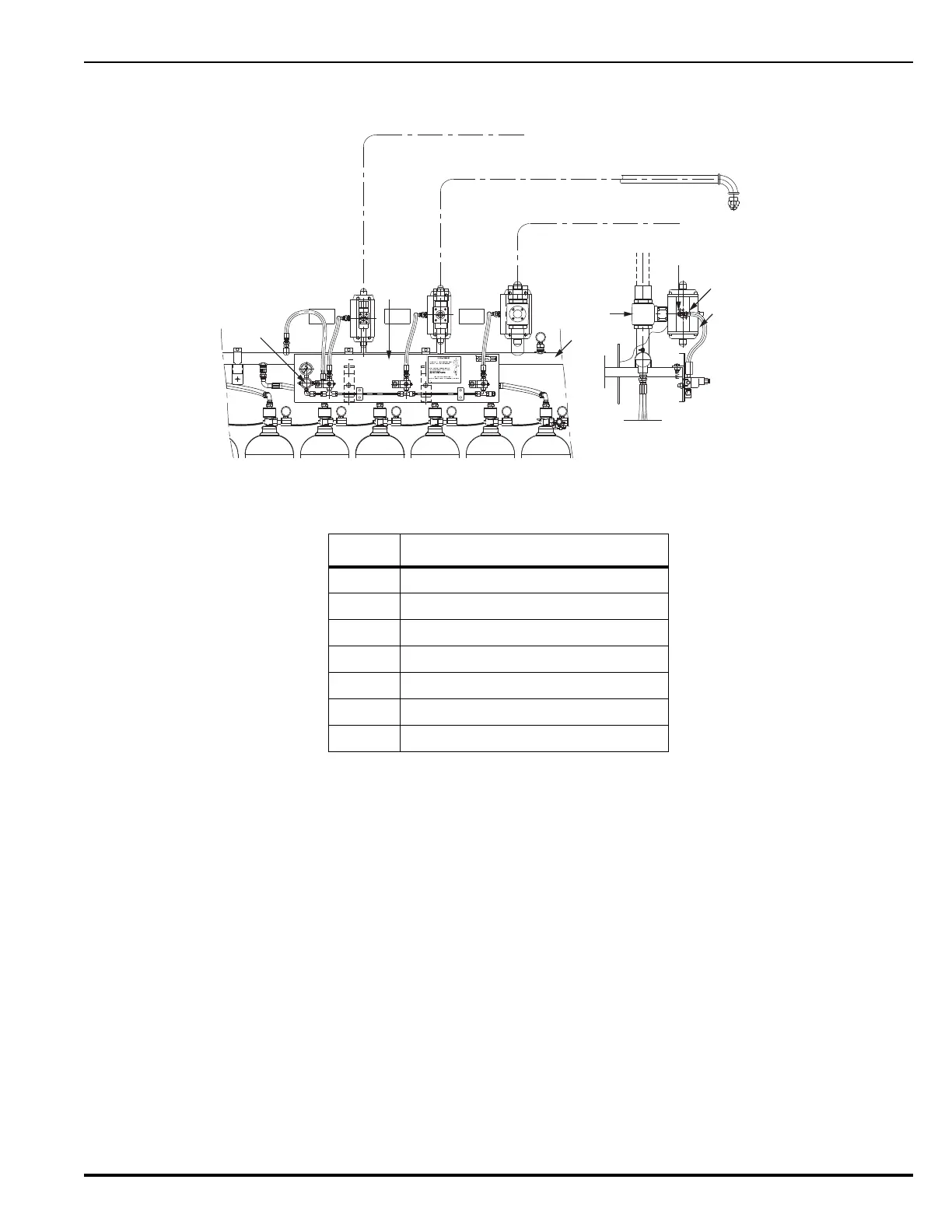
Figure 4-3 shows the Distribution manifold in a selector valve system including the selector
valves and backplate manifold. Not all release units are shown in the image.
Figure 4-3. Typical Detailed Cylinder Bank Selector Valve System
Table 4-3. Selector Valve System Cylinder Bank Arrangement Components
Item Description
1 Selector Valve Actuator
2 Connection for 1/4” Hi-flex hose
3 Actuator Vent Outlet
4Selector Valve
5 Discharge Manifold
6 Back-plate Manifold
7 Pressure Reducing Valve
NOZZLE INSTALLATION, TYPICAL
TO DISTRIBUTION PIPE WORK
ZONE 1
TO DISTRIBUTION PIPE WORK
ZONE 2
TO DISTRIBUTION PIPE WORK
ZONE 3
A
-Kerr