Chapter 1: Installation and wiring
20 P/N 3102351-EN • REV 005 • ISS 28DEC18
• Continuous circuit (AUX power 1): 24 VDC nominal at 500 mA (up to 1 Amp of alarm
current is available on AUX 1 if you reduce the total available control panel NACs alarm
current by the total amount of AUX 1 + AUX 2 alarm current over 500 mA). Use this circuit
to supply 24 VDC continuous power. A SMK module is required when using the UM or
MAB module to support two-wire smoke detectors.
• Resettable circuit (AUX power 2): 24 VDC nominal at 500 mA (standby and alarm). Use
this circuit to provide 24 VDC resettable power. You can configure AUX power 2 as a
continuous circuit if you do not need a resettable circuit.
• Special application circuits
• Ground fault impedance: 0 to 5 kΩ
• Supervised and power-limited
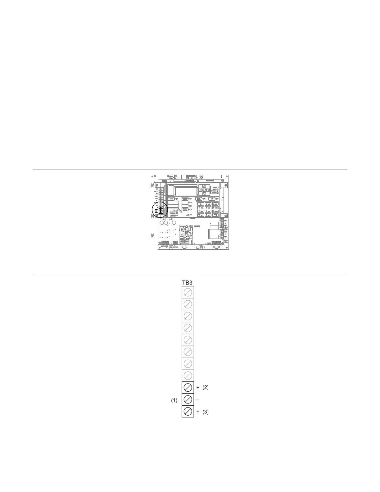
Figure 26: Auxiliary/smoke power wiring location
Figure 27: Auxiliary/smoke power output terminals
(1) Auxiliary/Smoke power output
(2) Resettable (AUX 2)