1
st
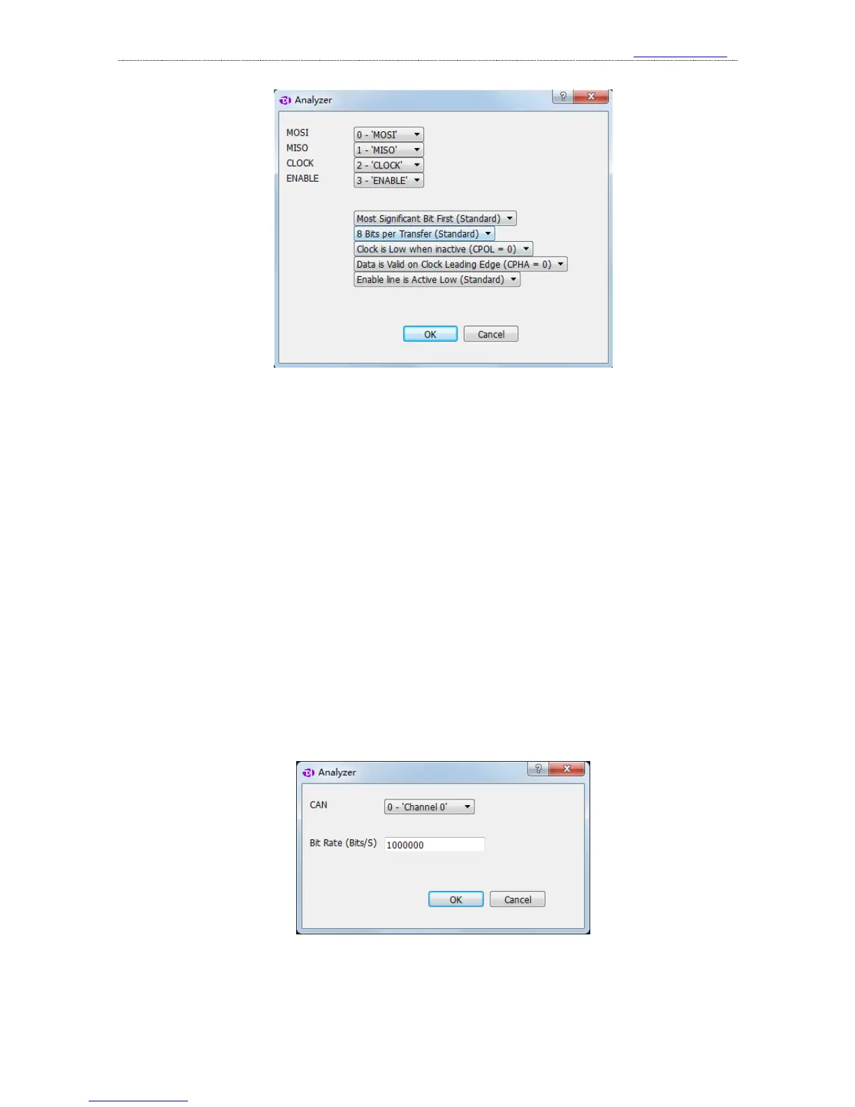
item, the channel for MOSI signal(master out slave in)
2
nd
item, the channel for MISO signal(master in slave out)
3
rd
item, the channel for CLOCK signal(clock)
4
th
item, the channel for ENABLE signal(enable)
5
th
item, transmission mode of data bits: MSB(Most Significant Bit First) or LSB(Least
Significant Bit First), usually MSB.
6
th
item, data length for one transfer, usually 8 or 16 bits.
7
th
item, idle state of the clock. CPOL = 0: the clock wire remains low in idle state. CPOL = 1:
the clock wire remains high in idle state.
8
th
item, the edge in which data is latched. CPHA=0: data latched in last clock edge. CPHA=1:
data latched in next clock edge.
9
th
item, the active level of enable signal: active low(Enable line is Active Low) or active
high(Enable line is Active High).
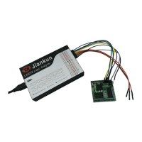
4、 CAN
The setting dialog of CAN analyzer is shown below:
1
st
item, the channel to use.
2
nd
item, baud rate in communication.
Please note that the signal from CAN bus is differential, there are 3 ways to measure CAN