F.
Pl
ace
the speed control connecting link (13) in position
with the bent end up toward
top
of
housing. Lay the switch
bracket and cam plate
(1
0)
on the housing and screw in the
two screws (8) with lock washers (9).
Put
the control link
(13) on the stud in end
of
switch lever ( 4
).
Place the switch
control link
on
stud near knob
of
switch lever.
Place
spring
( 15) under the control link ( 13) so
that
ends
of
spring are up
and rest
aga
inst the gear case bosses. This spring will provide
pr
ess
ur
e to hold
the
control link (13)
on
the switch lever (4).
G.
Check
th
e armature on a growler
or
take
th
e armature to
an electric
motor
repair shop and let
th
em test it.
If
it
is
not
in
good condition, replace
it
with a new one.
If
the old
armature is equipped with a thrust ball bearing and
it
is
still
good, pull it
off
th
e shaft with a gear puller. Slide the washer
on
th
e co
mmutator
end
of
the new armature.
Place the ball
bearing
on
th
e shaft with open side toward end
of
shaft. Seat
it with a sleeve and hammer.
Place
other
washer
on
open side
of
bearing. If
th
e old arma
tur
e
is
equipped with a thrust
sleeve bearing,
th
e complete bearing assembly (20,
21, 22,
23) should be replaced
if
necessary.
12
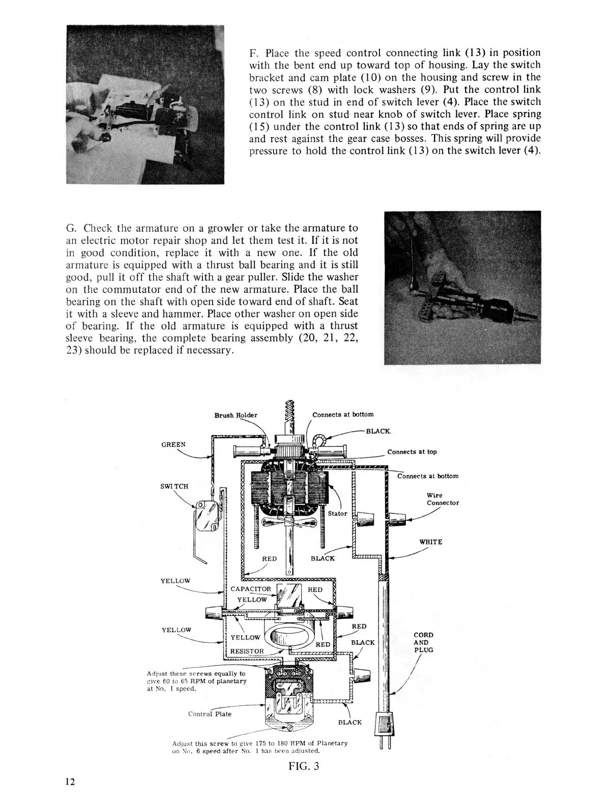
GREEN
YELLOW
Adjus
t
thi
s
sc
rew
to
~
i
v
e
175 to 1
80
RPM
of
P13netary
on
:--.:
o .
6 speed
after
No
.
1
ha
s
lx
•c n
adj
ust
e
d.
FIG. 3
Connects
at
bottom
Wire
CORD
AND
PLUG