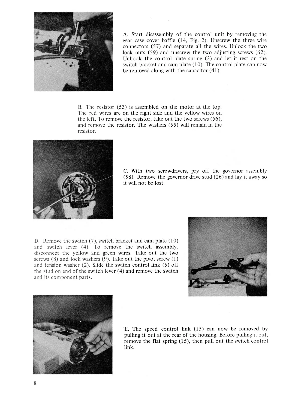
A.
Start
disassembly
of
the control unit by removing the
gear case cover baffle (14, Fig. 2). Unscrew
th
e
thr
ee wire
connectors (57) and separate all the wires. Unlock the two
lock nuts (59) and unscrew the two adjusting screws (62).
Unhook
the
control plate spring (3) and let it r
es
t on the
switch bracket and cam plate
(I
0). The control plate can now
be removed along with the capac
itor
(
41
).
B.
The resis
tor
(53)
is
assembled on the
motor
at the
top
.
The red wires are on the right side and
the
yellow wires on
the left. To remove the resistor, take
out
the two screws (56),
and remove the resistor. The washers (55) will remain in
th
e
resistor.
C.
With two screwdrivers, pry
off
the governor assembly
(58). Remove
the
governor drive stud (26) and lay it a
wa
y
so
it will
not
be lost.
D.
Remove the switch (7), switch bracket and cam plate
(I
0)
and
sw
itch lever ( 4
).
To remove the switch assembly,
disconnect the yellow and green wires. Take
out
the two
screws (8) and lock washers (9). Take
out
the pivot screw
(I)
and tension washer (2).
Slide
the switch control link (5)
off
the stud on end
of
the switch lever ( 4) and remove the switch
and its component parts.
8
E.
The speed control link (13) can now be removed by
pulling it
out
at
the
rear
of
the housing. Before pulling
it
out
,
remove the flat spring (15), then pull
out
th
e switch control
link.