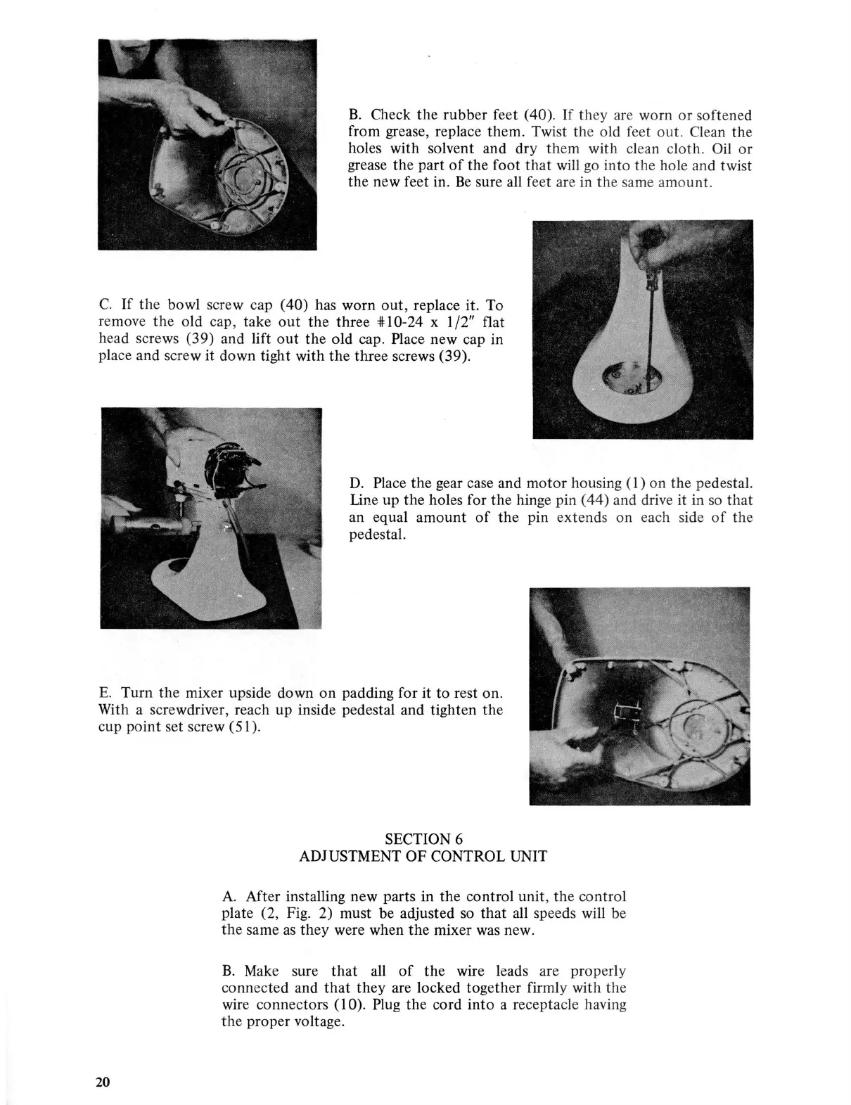
B.
Check
the
rubber feet (40). If they are worn
or
softened
from grease, replace them. Twist
th
e old feet out. Clean the
holes with solvent and dry them with
cl
ean cloth. Oil or
grease the part
of
the foot
that
will go into
th
e hole and t
wis
t
the new feet in.
Be
sure all feet are in
th
e same amount.
C.
If
th
e bowl screw cap ( 40) has worn
out,
replace it. To
remove
the
old cap, take
out
the
three
oll:
10-24 x 1 /2" flat
head screws (39) and lift
out
the
old cap. Place new cap in
place and screw it down tight with the three screws (39).
D.
Place
the
gear case and
motor
housing ( 1)
on
the pedestal.
Line up the holes for
the
hinge pin (
44)
and drive it in
so
that
an equal
amount
of
the
pin extends on each side
of
the
pedestal.
E.
Turn
the
mixer upside down
on
padding for it
to
rest on.
With a screwdriver, reach up inside pedestal and tighten
the
cup point set screw (51).
20
SECTION 6
ADJUSTMENT
OF
CONTROL UNIT
A.
After installing new parts in the control unit,
th
e control
plate (2, Fig. 2) must be adjusted
so
that
all
speeds will be
the
same
as
they were when
the
mixer was new.
B. Make sure
that
all
of
the
wire leads are properly
connected and
that
they
are locked together firmly with the
wire connectors ( 1 0). Plug
the
cord
into
a receptacle having
the
proper voltage.