43
■
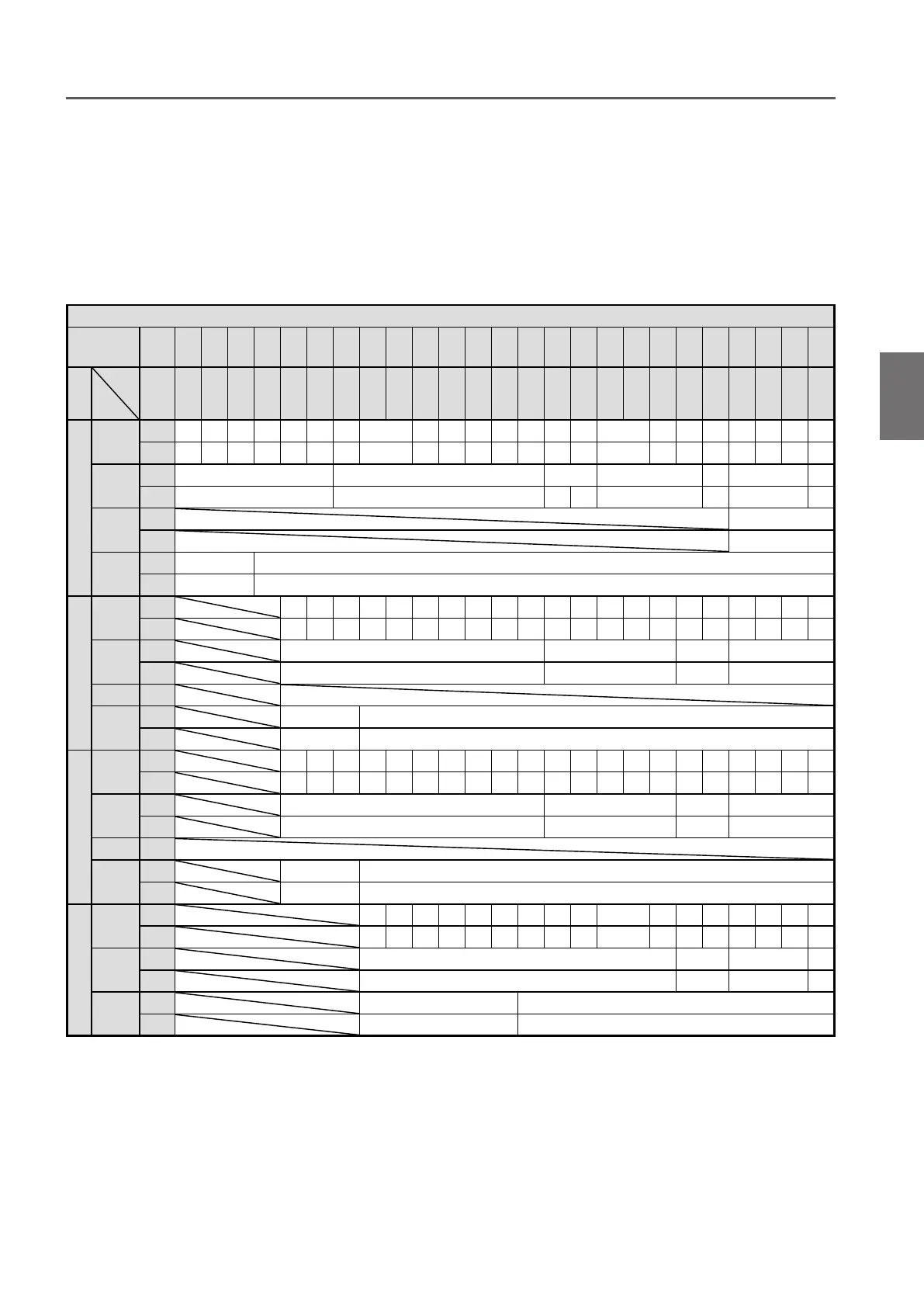
Checking the Number of the Assembled Adjusting Spacers and Their Positions
When installing a trolley to the beam, the length of the Suspension Shaft (width between frames) must be adjusted in
accordance with the rail width.
Wrong number of wrong position of Spacers may result in the drop of the electric chain hoist.
Insert the correct number of Spacers with correct ratings and for rail width at the correct position, referring to the
following table.
(to be continued)
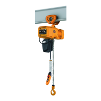
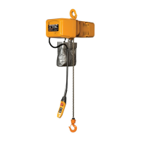
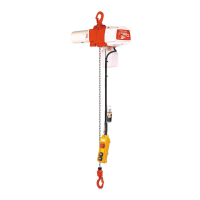
Assembling Combining with the motorized trolley
1
Number of Adjusting Spacers
Beam flange
width
(in)
2
5
/
16
2
1
/
2
2
5
/
8
2
7
/
8
2
15
/
16
3
3
1
/
4
3
9
/
16
3
7
/
8
3
15
/
16
4
4
3
/
16
4
5
/
16
4
7
/
16
4
11
/
16
4
3
/
4
4
15
/
16
5
5
3
/
16
5
5
/
16
5
3
/
8
5
5
/
8
5
11
/
16
5
3
/
4
6
6
1
/
8
6
5
/
16
6
7
/
16
6
11
/
16
Capacity(t)
Parts
Name
(mm) 58
64
66
73
74
75
76
82
90
91
98 100 102 106 110 113
119
120
125 127 131 135 137 143
149
150
153 155 160 163 170
1
Thin spacer
Inner
1+2 2+3 4+4 1+0 1+2 2+3 0 1+0 1+2 2+2 2+3 3+4 4+4 4+1 5+1 2+2 3+3 4+4 4+1 1+1 2+2 2+3 3+0
Outer
5 3 0 7 5 3 8 7 5 4 3 1 0 3 2 4 2 0 3 6 4 3 5
Thick spacer
Inner
0 1+1 1+2 2+2 2+3 3+3 3+4
Outer
5 3 0 2 1 0 3 2
Fixing spacer
Inner
0
Outer
2
Thick spacer L
Inner
0 1+1
Outer
2 0
2
Thin spacer
Inner
1+2 2+3 3+4 0 1+0 1+1 1+2 2+2 3+3 4+4 1+0 1+1 1+2 2+2 3+3 4+0 4+1 1+1 1+2 2+2 3+3
Outer
5 3 1 8 7 6 5 4 2 0 7 6 5 4 2 4 3 6 5 4 2
Thick spacer
Inner
0 1+1 1+2 2+2
Outer
5 3 2 1
Fixing spacer
Inner
Thick spacer L
Inner
0 1+1
Outer
2 0
3
Thin spacer
Inner
1+2 2+3 3+4 0 1+0 1+1 1+2 2+2 3+3 4+4 1+0 1+1 1+2 2+2 3+3 4+0 4+1 1+1 1+2 2+2 3+3
Outer
5 3 1 8 7 6 5 4 2 0 7 6 5 4 2 4 3 6 5 4 2
Thick spacer
Inner
0 1+1 1+2 2+2
Outer
5 3 2 1
Fixing spacer
Inner
Thick spacer L
Inner
0 1+1
Outer
2 0
5
Thin spacer
Inner
0 1+0 1+1 1+2 2+2 3+3 0 1+0 1+1 2+2 3+3 4+0 4+1 1+1 2+2 2+3 3+0
Outer
8 7 6 5 4 2 8 7 6 4 2 4 3 6 4 3 5
Thick spacer
Inner
0 0+1 1+1 1+2
Outer
3 2 1 0
Thick spacer L
Inner
0 1+1
Outer
2 0
●
Adjusting spacer arrangement for LOW Head Suspension (Beam flange width 58-170mm)
Remarks) 1) Description for inner spacers
For example, 0+1
0 : the number of spacers on the left side of the shaft
1 : the number of spacers on the right side of the shaft
2) Adjustment of trolley width
Refer to page 45.
Adjust the dimensions by appropriately increasing or decreasing the number of inner or outer adjusting
spacers shown in the above table.