CPU Holder Mount Kit
Pattern Number Represented:
CPU Holder Mount Kit, YACPU
Parts List:
CPU Holder Adaptor Bracket (A)
¼-14 x
7
/
8
" Wood Screw (B)
10–32 x ½" Machine Screw (C)
Track from KnollExtra CPU Holder
Tools Needed:
Drill
Phillips #2 and #3 bits
STEPS
NOTE: Knoll CPU Holder Mount Kits are intended
for use with KnollExtra CPU Holders only.
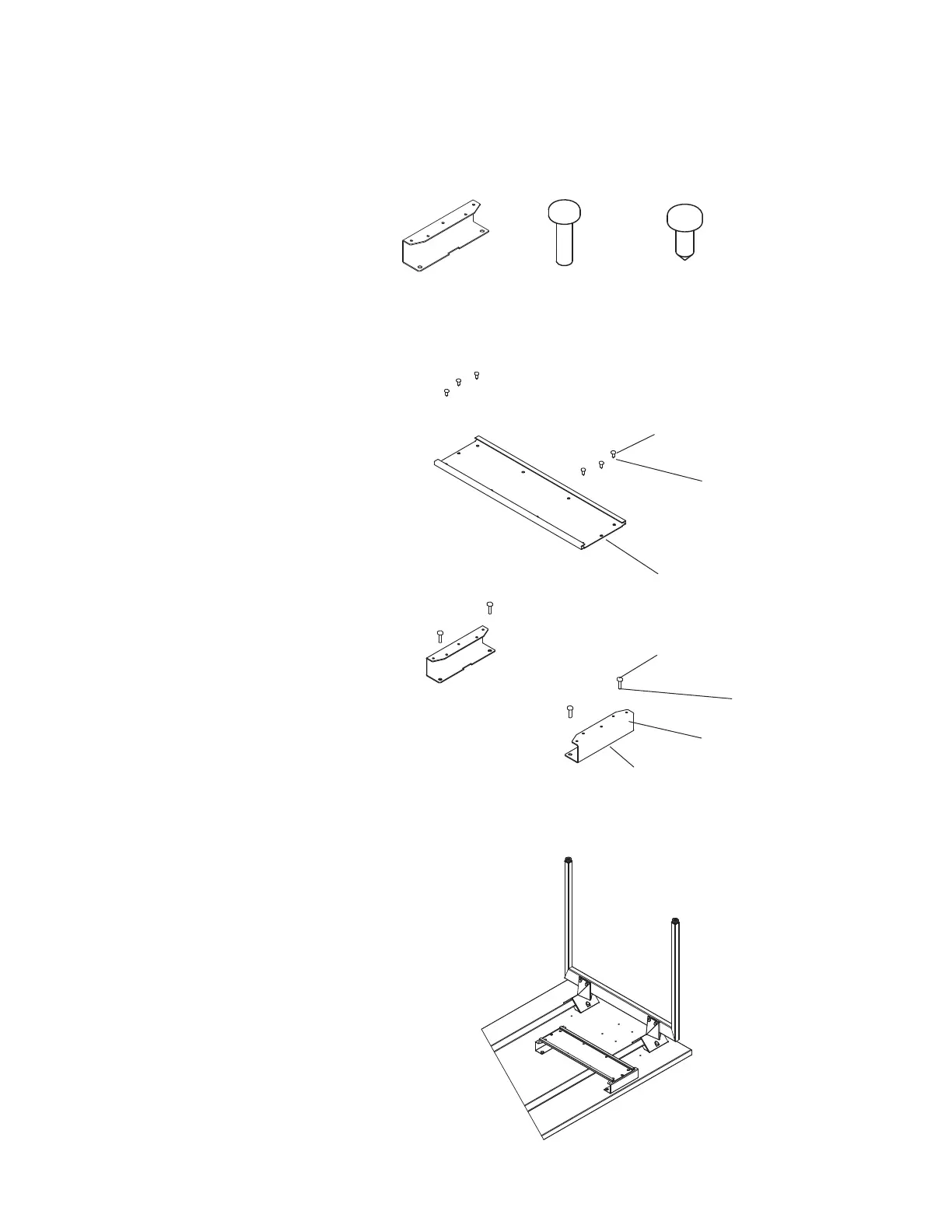
1. Position (2) CPU holder adaptor brackets (A) on
a flat surface, oriented as shown in exploded
CPU holder mount diagram at right. The sides
of the brackets with five holes should face up.
2. Attach the track to the CPU holder adaptor
brackets (A) using (3) 10-32 x ½" machine
screws (C) for the back bracket, and (3) 10-32
x ½" machine screws (C) for the front bracket.
3. Position the CPU holder adaptor bracket/
track assembly under the worksurface
so that the front bracket is inset ½" -1"
from the front edge of the worksurface.
Adjust alignment as required to clear any
suspended electrical/ data components.
4. Attach the CPU holder adaptor bracket/
track assembly (A) to the underside of
the top with (2) ¼-14 x
7
/
8
" wood screws
(B) per bracket (4 total screws).
NOTE: Please refer to the instructions
packaged with the KnollExtra CPU
Holder further assembly instructions.
(A) 3 AB 8026111 (B) 4A214020140 (C) 7083440
Step 2
10 - 32 x
½" Machine
Screw (C)
Track from
KnollExtra
CPU Holder
Step 4
¼ - 14 x
7
/
8
" Wood
Screw (B)
CPU Holder
Adaptor
Bracket (A)
Step 1
Exploded Keyboard Tray
Mount Assembly
Assembled CPU Holder Mount