STEPS
Sliding Door Pre-Assembly
1. (If not factory installed) Fasten the housings
(A) to the back of doors into the factory
drilled pockets using fastener (B). (Fig. 2)
2. (If not factory installed) Using a hammer, insert
the press-fit guide(s) (C) into the factory drilled
hole(s) on the inside surface of the bottom shelf
oriented with the flats of the guide parallel to
the front edge of the bottom shelf. (Fig. 3)
3. At each end of the factory installed
support rail you will find a rectangular
cut-out, using this as an access point,
install all the running gears (D). (Fig. 4)
4. Once all the running gears are installed
onto the track(s), insert one stopper
(E) at each end. (Fig. 5A & 5B)
Sliding Door Installation
1. Line the bottom track on the back of the
door with the guides on the bottom shelf,
rotating the door up, align the running
gears with the housings and snap into
place. Repeat this for each door. (Fig. 6)
2. (If required) The doors can be leveled using
the gear mechanism on the running gears
which provides
1
/
8
" of adjustment up and
down for a total of ¼" adjustability. (Fig.7)
Wall Mounted Overhead Cabinet Sliding Doors
Pattern Numbers Represented:
Sliding Door Set, YSSD___
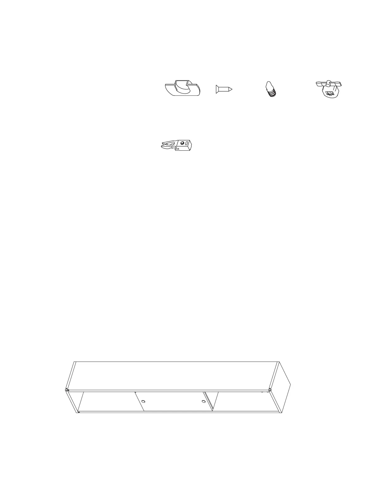
Parts List:
Housing (A)
Fastener (B)
Guide (C)
Running Gear (D)
Stopper (E)
Overhead Cabinet
Sliding Doors
Tools Needed:
Measuring Tape
8
/
16
" Diameter Drill
Square Drive Screw Driver
(A) 6TP40330 (B) 6TP40335 (C) 6TP40333 (D) 6TP40331
(E) 6TP40332
Reff Profiles
™
February 24, 2011
Reff Profiles
™
Installation Instructions
Sliding Door Pre-Assembly
1. (If not factory installed) Faten the housings
(A) to the back of doors into the factory
drilled pockets using fastener (B). (Fig. 2)
2. (If not factory installed) Using a hammer,
insert the press-fit guide(s) (C) into the
factory drilled hole(s) on the inside surface
of the bottom shelf oriented with the flats
of the guide parallel to the front edge of the
bottom shelf. (Fig. 3)
3. At each end of the factory installed support
rail you will find a rectangular cut-out, using
this as an access point, install all the
running gears (D). (Fig. 4)
4. Once all the running gears are installed
onto the track(s), insert one stopper (E) at
each end. (Fig. 5A & 5B)
Sliding Door Installation
1. Line the bottom track on the back of the
door with the guides on the bottom shelf,
rotating the door up, align the running
gears with the housings and snap into
place. Repeat this for each door. (Fig. 6)
2. (If required) The doors can be levelled using
the gear mechanism on the running gears
which provides 1/8" of adjustment up and
down for a total of 1/4" adjustability. (Fig. 7)
Overhead Sliding Door
Part# 6TP00088
Parts List - Hardware
(A) 6TP40330
HOUSING
(B) 6TP40335
FASTENER
(C) 6TP40333
GUIDE
(C) 6TP40331
RUNNING GEAR
(D) 6TP40332
STOPPER
Tools Needed
Measuring Tape
8/16" Diameter Drill
Square Drive Screw Driver
reff_profiles_ii_d_13_b.eps at 50%
reff_profiles_ii_d_13_b.eps at 50%
reff_profiles_ii_d_13_b.eps at 50%
reff_profiles_ii_d_13_b.eps at 50%
reff_profiles_ii_d_13_b.eps at 50%
Fig. 2 Fig. 3
Fig. 5A
Fig. 5B
Fig. 6A Fig. 7
Fig. 6
Fig. 4
Fig. 1
C
B
C
D
E
E
Rotate gear to adjust
door height
Rotate
upward
Align bottom track
of door with
guide pin
Tighten set screw to
keep stopper in place
Reff Profiles
™
February 24, 2011
Reff Profiles
™
Installation Instructions
Sliding Door Pre-Assembly
1. (If not factory installed) Faten the housings
(A) to the back of doors into the factory
drilled pockets using fastener (B). (Fig. 2)
2. (If not factory installed) Using a hammer,
insert the press-fit guide(s) (C) into the
factory drilled hole(s) on the inside surface
of the bottom shelf oriented with the flats
of the guide parallel to the front edge of the
bottom shelf. (Fig. 3)
3. At each end of the factory installed support
rail you will find a rectangular cut-out, using
this as an access point, install all the
running gears (D). (Fig. 4)
4. Once all the running gears are installed
onto the track(s), insert one stopper (E) at
each end. (Fig. 5A & 5B)
Sliding Door Installation
1. Line the bottom track on the back of the
door with the guides on the bottom shelf,
rotating the door up, align the running
gears with the housings and snap into
place. Repeat this for each door. (Fig. 6)
2. (If required) The doors can be levelled using
the gear mechanism on the running gears
which provides 1/8" of adjustment up and
down for a total of 1/4" adjustability. (Fig. 7)
Overhead Sliding Door
Part# 6TP00088
Parts List - Hardware
(A) 6TP40330
HOUSING
(B) 6TP40335
FASTENER
(C) 6TP40333
GUIDE
(C) 6TP40331
RUNNING GEAR
(D) 6TP40332
STOPPER
Tools Needed
Measuring Tape
8/16" Diameter Drill
Square Drive Screw Driver
reff_profiles_ii_d_13_b.eps at 50%
reff_profiles_ii_d_13_b.eps at 50%
reff_profiles_ii_d_13_b.eps at 50%
reff_profiles_ii_d_13_b.eps at 50%
reff_profiles_ii_d_13_b.eps at 50%
Fig. 2 Fig. 3
Fig. 5A
Fig. 5B
Fig. 6A Fig. 7
Fig. 6
Fig. 4
Fig. 1
C
B
C
D
E
E
Rotate gear to adjust
door height
Rotate
upward
Align bottom track
of door with
guide pin
Tighten set screw to
keep stopper in place
Rotate gear to adjust
door height
Rotate
upward
Align bottom track
of door with
guide pin
Tighten set screw to
keep stopper in place
Figure 1
 Loading...