Fabric Intermediate Screens - Partial Depth
for Use with Tops with Hinged Access
Pattern Numbers Represented:
Fabric Intermediate Screens, YPSI__F
Parts List:
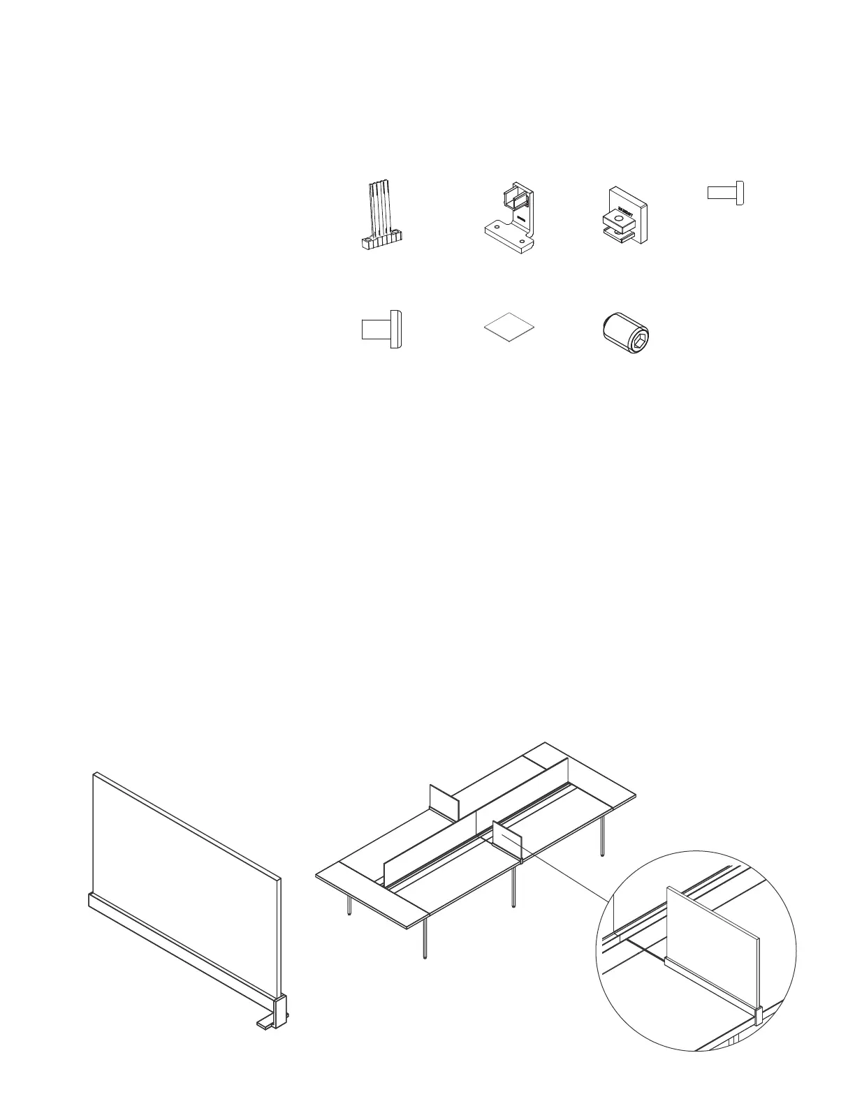
Bayonet Mount Bracket (A)
Upholstered Intermediate Screen Rail Clamp (B)
Upholstered Intermediate Screen Rail End Cap (C)
5
/
16
-18 x ¾" Machine Screw (D)
¼ - 20 x
3
/
8
" Black Oxide Machine Screw (E)
Non-Skid Pad (F)
¼ - 20 x
3
/
8
" Set Screw (G)
Screen Bottom Extrusion
Screen
Tools Needed:
Drill
Phillips #2 and #3 bits
1
/
8
" Allen Key
STEPS
1. Insert (2) bayonet mount brackets (A) into
the top of the screen bottom extrusion so
that the holes in the brackets align with
the two sets of holes in the extrusion.
2. Insert (4)
5
/
16
-18 x ¾" machine screws (D)
beneath the extrusion and firmly attach the (2)
bayonet mount brackets (A) to the extrusion.
3. Insert (1) upholstered intermediate
screen rail end cap (C) into one end
of the bottom screen extrusion.
4. Insert (1) hex head set screw (G) into the end cap
(C) and secure it to the bottom screen extrusion.
5. Peel the protective paper from one side
of the non-skid pad (F) to expose one
of the adhesive sides.
6. Affix the non-skid pad (F) to the underside
of the bottom screen extrusion close to the
end cap (C) that has just been attached.
NOTE: DO NOT REMOVE THE OTHER SIDE
OF THE PROTECTIVE PAPER AT THIS POINT.
7. Determine the desired screen position along
the width of the table, and position the screen
extrusion on the worksurface accordingly.
8. Hook (1) upholstered intermediate screen rail
clamp (B) to the front edge of the worksurface
so that the clamp’s u-channel is above the
worksurface and the two screw holes are below
the worksurface. Slide the open end of the
bottom screen extrusion onto the u-channel
portion to temporarily support the bracket.
9. Lifting the free end of the screen assembly
slightly, carefully peel the protective paper
from the other side of the non-skid pad
(F), then firmly press the screen assembly
downward to adhere the free end of the
bottom screen extrusion to the worksurface.
10. Insert (2) ¼ - 20 x
3
/
8
" black oxide machine
screws (E) into the holes under the rail clamp
(B). Hold the U-channel portion of the rail
clamp (B) firmly against the side of the screen
bottom extrusion and tighten the screws
against the bottom of the worksurface.
NOTE:The ¼ - 20 x
3
/
8
" black oxide machine
screws (E) are to be treated as set screws and
will create the tight connection between the
screen bottom extrusion and the worksurface.
The rail clamp (B) must be seated firmly within
the side of the bottom extrusion, but should not
be pressed tight against the bottom of the
worksurface. A space will remain between the
rail clamp and the bottom of the worksurface.
11. Position the openings in the underside
of the screen over the bayonet mount
brackets (A) and push the screen down
until the screen is firmly seated.
(A) 3AB408200 (B) 3AB1206* (C) 3AB1207* (D) 7060440
(E) 7019440 (F) 3AB419700 (G) 4A2200740
Intermediate Screens
Planning and Specification Guidelines
Antenna Workspaces
142
Intermediate Screens
Planning and Specification Guidelines
Antenna Workspaces
142
Partial Depth Intermediate Screen
for Use with Hinged Access Tops
Big Table with Hinged Access Tops and
Partial Depth Intermediate Screens