10.3
Section 10
Reassembly
10
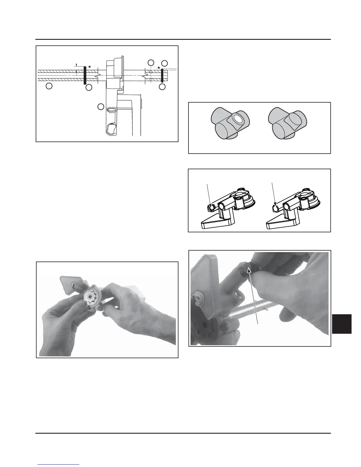
Figure 10-6. Assembled Intake Cam Shaft Details.
1. Intake Cam Sha
2. 3 mm Diameter Pin
3. Oil Pump Assembly
4. 2.5 mm Diameter Pin
5. #1 Hole Location
6. #2 Hole Location
2. If it was removed, install and center the longer,
3 mm diameter drive pin into the upper hole (See
Figure 10-6).
3. Lightly grease the gerotor gears and install into
the oil pump, with the short drive pin fied into
the slot of the inner gear. See Figure 10-7.
Figure 10-7. Gerotor Gears Installed in Oil Pump.
4. Determine if the outlet of the oil pump is open or
closed. See Figure 10-9. The open style pumps
require the use of a rubber seal between the
pump outlet and lower main bearing area. See
Figure 10-8. Some models use an open style seal
with an internal passage to feed oil to the lower
bearing. Some models use a closed seal without
an oil passage, and the cranksha is crossed-
drilled for lower bearing lubrication. Both styles
of outlet seals are shown in Figure 10-9. If a new
seal is to be ordered, be sure it is the same style
as the one that was taken out. Lightly lubricate
the ends of the oil pump outlet seal with oil and
install in into the outlet of the oil pump. See
Figure 10-10.
5
1
4
3
2
6
Pump Outlet Seal
Open Outlet Style
(Requires Seal)
Closed Outlet Style
Open Seal Closed Seal
Figure 10-10. Installing Oil Pump Outlet Seal.
Figure 10-8. Pump Outlet Seals.
Figure 10-9. Oil Pump Outlet Styles.
 Loading...


