5.16
Section 5
Fuel System and Governor
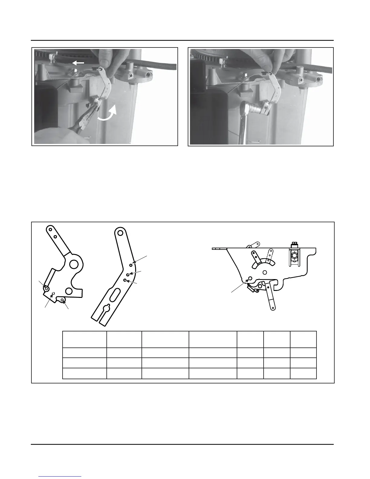
Figure 5-27. Early Style Governor Spring Location Chart.
Governor
Lever
Throttle
Lever
Single
Alignment
Hole
1
2
3
High Speed
RPM
Governed
Idle RPM
Governed
Lever Hole No.
Throttle Lever
Hole No.
White
Spring
Green
Spring
Black
Spring
;
;
;
1
3
2
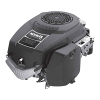
Figure 5-25. Governor Adjustment.
Figure 5-26. Tightening Governor Lever Nut.
Governor Sensitivity Adjustment
Governor sensitivity is adjusted by repositioning the governor spring in the holes in the governor lever. If speed
surging occurs with a change in load, the governor is set too sensitive. If a big drop in speed occurs when a
normal load is applied, the governor should be set for greater sensitivity.
The desired high speed seing (RPM) will determine the governor spring position in the governor lever and the
throle lever, as well as the spring used. See Figure 5-27 and 5-28.
 Loading...


