10.11
Section 10
Reassembly
10
Figure 10-37. Assembling Cylinder Head.
Install Cylinder Head
NOTE: Do not reuse cylinder head screws or gasket,
always replace with new parts.
1. Check to make sure there are no nicks or burrs
on the sealing surfaces of the cylinder head or
crankcase.
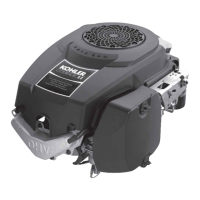
Figure 10-36. Closure Plate Fastener Torque
Sequence.
Assemble Cylinder Head
Prior to assembly, lubricate all the components with
engine oil, including the tips of the valve stems and
valve guides. Using a valve spring compressor, install
the following items in the order listed. See Figure
10-37.
• Intake and exhaust valves
• Valve spring caps
• Valve springs
• Valve spring retainers
• Valve spring keepers
5
1
3
7
10
8
9
12
4
2
6
11
14
13
NOTE: If the cranksha has not been turned
since the installation of the crank gear,
turn it one (1) complete revolution. This
will set the piston at top dead center
(TDC) of the compression stroke, for
proper valve lash adjustment later.
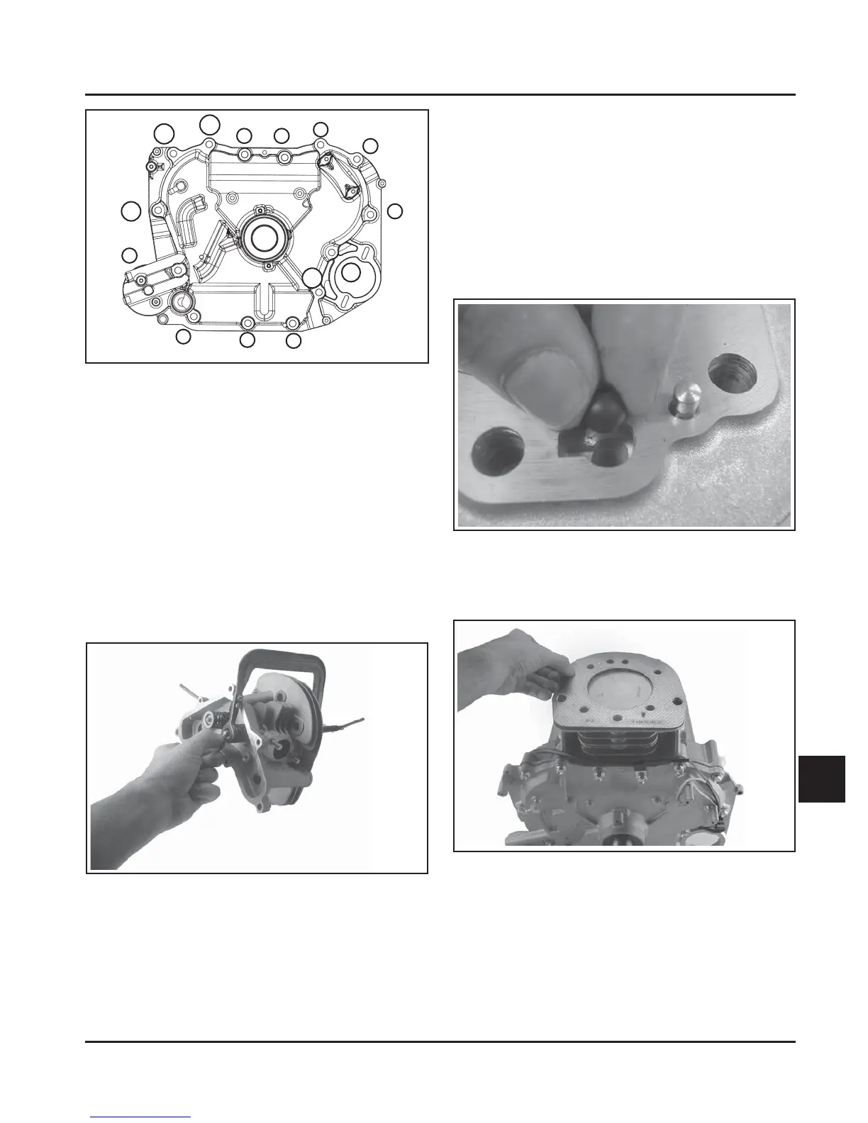
2. If the engine uses a drain back check ball, install
it into the keyhole slot in the top of the crankcase.
See Figure 10-38.
Figure 10-38. Installing Drain Back Check Ball.
(Some Models)
3. Install a new cylinder head gasket. See Figure
10-39.
Figure 10-39. Installing Head Gasket.
4. Install the cylinder head and start the six hex
flange screws. Install the thick washer on the
screw closest to the exhaust port. See
Figure 10-39.
 Loading...


