10.5
Section 10
Reassembly
10
PTO Side
Guide Pin
Figure 10-14. Assembling Balance Weight to
Crankshaft (Guide Shoe Design).
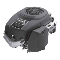
Engines Serial No. 3618005223 and Above:
c. Align the weights and insert the balance
weight screw, through the mounting holes
from the flywheel side. Thread it into the
guide pin outside the weight on the PTO side.
Hold the guide pin with a wrench or Torx bit,
and torque the screw to 11.3 N·m (100 in. lb.).
See Figure 10-15. Do not hold, or damage the
outside diameter (O.D.) of the guide pin.
Apply grease to the inner diameter (I.D.) of
each hole in control link and install one end
over the guide pin.
Figure 10-15. Assembling Balance Weight to
Crankshaft (Control Link Design).
Figure 10-16. Installing Crank Gear Key.
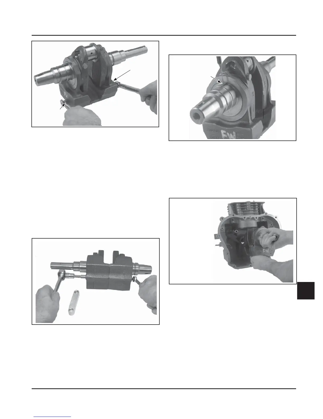
Engines Serial No. 3618005213 and below:
3. Carefully install the cranksha into crankcase,
through the PTO seal, and seat fully into place.
Rotate the cranksha so that the journal for the
connecting rod is away from the cylinder. See
Figures 10-17.
Crank Gear Key
Figure 10-17. Installing Crankshaft Assembly
(Before Serial No. 3618005213).
4. Install the balance weight guide shoe onto
the guide pin with the solid end toward the
cranksha. See Figure 10-18.
2. Carefully install crank gear key in keyway.
See Figure 10-16.
 Loading...


